

Rotary worktable for free forging
A technology for rotating worktable and forging, applied in the field of worktable and free forging rotating worktable, can solve the problems of hidden danger of worktable, low work efficiency, scrapped workpiece, etc., so as to reduce labor intensity, save labor cost, reduce Effect of small turning torque
- Summary
- Abstract
- Description
- Claims
- Application Information
AI Technical Summary
Problems solved by technology
Method used
Image

Examples
Embodiment 1
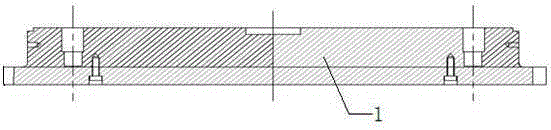
[0041] Example 1: see Figure 1-Figure 13, a rotary table for free forging, the rotary table includes a motor, a reducer, a coupling arranged between the motor and the reducer, the table also includes a lower pier connecting seat 1, a rotary table Spring seat 2, rotating table spring 3, rotating table circular slideway 4, rotating table steel ball 5, rotating table lower upsetting backing plate 6, rotating table’s lower upsetting seat 7, rotating table’s lower pier mandrel 8 , Upsetting mandrel bushing 9 under the rotating workbench, the large ring gear 10 of the rotating worktable, the pinion 11 of the rotating workbench, the brake device 12 of the rotating workbench, wherein the pinion 11 is connected with the reducer through a shaft, and the pinion 11 of the The other end is connected with the large ring gear 10, the large ring gear 10 is set on the outer ring of the lower pier backing plate 6 and welded with the lower pier backing plate 6, the lower abutment 7 is arrange...
Embodiment 2
[0042] Example 2: see Figure 1-Figure 13 , as an improvement of the present invention, the workbench also includes an annular slideway 4 and a steel ball 5, the annular slideway 4 is supported on the spring of the lower upsetting seat connection seat, and the steel ball supports the lower upsetting seat backing plate above, The annular slideway 4 is provided with a groove ring 5, the steel ball 5 is placed in the groove ring on the annular slideway, and the inner ring groove is arranged on the connecting seat, and the inner ring groove of the connecting seat positions the annular slideway 4 . When the table rotates, the steel balls produce rolling friction with the lower upsetting backing plate. The technical scheme is equipped with annular slideways and steel balls, which can effectively prevent the excessive rotation torque of the workbench or the phenomenon of burning the motor and reducer during the forging process of the forging. The rest of the structures and advant...
Embodiment 3
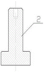
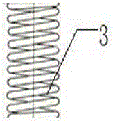
[0043] Example 3: see Figure 1-Figure 13 , as an improvement of the present invention, the workbench further includes a spring 3 , and the spring 3 is arranged on the spring seat 2 . It can ensure that the lower pier is in a suspended state when the worktable rotates to reduce the rotational torque, and can ensure that the force of the forging press hammer can be transmitted to the forging press base when the forging press hammer is pressed down, preventing the base from tipping and ensuring that the pressure surface of the forging is flat. The rest of the structures and advantages are exactly the same as in Embodiment 1.
PUM
 Abstract
Description
Claims
Application Information