Welding process for suction and exhaust pipe of liquid accumulator

A welding process and liquid reservoir technology, applied in welding equipment, manufacturing tools, metal processing equipment, etc., can solve the problems of high overall welding cost, low welding efficiency, and high overall cost, and achieve the effect of eliminating hidden leaks

Inactive Publication Date: 2016-01-13
WUHU SANHUA REFRIGERATION FITTINGS
View PDF11 Cites 6 Cited by
  • Summary
  • Abstract
  • Description
  • Claims
  • Application Information

AI Technical Summary

Problems solved by technology

[0016] 2) Hidden dangers of quality: First: Poor solder joint strength and tightness are unstable and there are hidden dangers of leakage;
[0017] 3) Cost: The overall cost of the existing process is relatively high for one-time welding or two-time welding
[0018] Although many welding processes for dissimilar materials have been disclosed in the prior art, the following problems still exist in the prior art for welding processes of dissimilar materials: 1. The welding process is complicated; 2. The overall cost of welding is high; 3. The welding efficiency is low ; 4. Poor solder joint strength and tightness, unstable welding and potential leakage

Method used


Image

  • Welding process for suction and exhaust pipe of liquid accumulator

Examples


Embodiment 1

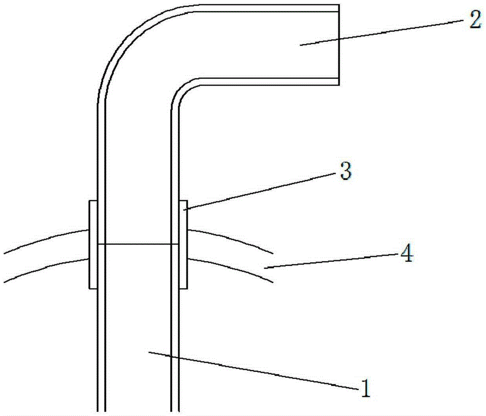
[0041] A welding process for the suction and exhaust pipes of a liquid reservoir, comprising a liquid reservoir, a small steel pipe and a copper bend, characterized in that a sleeve is provided at the connection between the small steel pipe and the copper bend, and the sleeve is stuck in the liquid reservoir At the through hole, the soldering process includes the following steps:

[0042] 1) Pre-welding treatment, including grinding and cleaning;

[0043] 2) Assembling the parts, clamping the ends of the small steel pipe and the copper elbow respectively in the casing to form a weldment;

[0044] 3) Welding;

[0045] 4) Clamp the sleeve of the weldment on the through hole of the reservoir for welding.

[0046] In the present embodiment, in step 1), grinding is performed on the small steel pipe and the copper elbow welding area and at least 20 mm around the area, grinding until metallic luster appears, removing oil stains and oxide films, and ensuring that the surface of the ...

Embodiment 2

[0056] A welding process for the suction and exhaust pipes of a liquid reservoir, comprising a liquid reservoir, a small steel pipe and a copper bend, characterized in that a sleeve is provided at the connection between the small steel pipe and the copper bend, and the sleeve is stuck in the liquid reservoir At the through hole, the soldering process includes the following steps:

[0057] 1) Pre-welding treatment, including grinding and cleaning;

[0058] 2) Assembling the parts, clamping the ends of the small steel pipe and the copper elbow respectively in the casing to form a weldment;

[0059] 3) Welding;

[0060] 4) Clamp the sleeve of the weldment on the through hole of the reservoir for welding.

[0061] In the present embodiment, in step 1), grinding is performed on the small steel pipe and the copper elbow welding area and at least 20 mm around the area, grinding until metallic luster appears, removing oil stains and oxide films, and ensuring that the surface of the ...

Embodiment 3

[0071] A welding process for the suction and exhaust pipes of a liquid reservoir, comprising a liquid reservoir, a small steel pipe and a copper bend, characterized in that a sleeve is provided at the connection between the small steel pipe and the copper bend, and the sleeve is stuck in the liquid reservoir At the through hole, the soldering process includes the following steps:

[0072] 1) Pre-welding treatment, including grinding and cleaning;

[0073] 2) Assembling the parts, clamping the ends of the small steel pipe and the copper elbow respectively in the casing to form a weldment;

[0074] 3) Welding;

[0075] 4) Clamp the sleeve of the weldment on the through hole of the reservoir for welding.

[0076] In the present embodiment, in step 1), grinding is performed on the small steel pipe and the copper elbow welding area and at least 20 mm around the area, grinding until metallic luster appears, removing oil stains and oxide films, and ensuring that the surface of the ...


PUM


Abstract

The invention discloses a welding process for a suction and exhaust pipe of a liquid accumulator. The liquid accumulator, a small steel pipe and a copper elbow pipe are included. A sleeve pipe is arranged at the joint of the small steel pipe and the copper elbow pipe, and the sleeve pipe is clamped at a through hole of the liquid accumulator. The welding process comprises the following steps of pre-welding processing including grinding and cleaning, component assembling, namely forming a weld assembly by clamping the end of the small steel pipe and the end of the copper elbow pipe in the sleeve pipe, and welding. As welding is carried out by clamping the sleeve pipe of the weld assembly at the through hole of the liquid accumulator, the potential hazards of leakage of a weld joint are reduced and eliminated; one-time welding or multi-time welding is carried out on copper pipes, iron pipes and other materials or structural products through different welding processes; the leakage rate is about hundreds of PPM through an existing conventional welding process; the leakage rate after improvement is about several PPM, and leakage is nearly eradicated.

Description

technical field [0001] The invention relates to the fields of refrigeration and pressure vessels, in particular to a welding process for suction and discharge pipes of a liquid receiver. Background technique [0002] In the welding process of dissimilar materials, due to the great gap between the chemical composition, thermal conductivity, melting point and various mechanical properties of the two, the difficulty of welding is much greater than that of similar materials. The performance is poor and unstable, and there is a hidden danger of leakage. The overall cost of one-time welding or two-time welding in the existing process is relatively high. [0003] In the prior art, many improvements have been made to address the above problems. For example, the publication number CN104551352A discloses a welding method for dissimilar metals, which is used for welding the shell connection end made of low alloy steel and the safety end made of stainless steel. The method comprises th...

Claims


Application Information

Patent Timeline
Patent Type & Authority Applications(China)
IPC IPC(8): B23K1/00B23K1/20
CPCB23K1/00B23K1/20B23K1/206
Inventor 樊锋胡泽华
Owner WUHU SANHUA REFRIGERATION FITTINGS
Why Eureka
Try Eureka