
Combustion boiler of power station

A combustion furnace and boiler technology, applied in the combustion chamber, combustion method, boiler water pipe, etc., can solve the problems of low power generation efficiency, low heat, and shortened boiler service life.

Active Publication Date: 2016-01-13
江苏橙果能源环保有限公司
View PDF8 Cites 3 Cited by
  • Summary
  • Abstract
  • Description
  • Claims
  • Application Information

AI Technical Summary

Problems solved by technology

During the use of the boiler, coking is a relatively common phenomenon in the operation of coal-fired boilers. It will destroy the normal combustion conditions, reduce boiler output, and disrupt normal water circulation and other undesirable phenomena. In severe cases, large coke pieces of the boiler will fall in the cold After entering the slag hopper, a large amount of water vapor is generated instantaneously, causing negative pressure fluctuations in the furnace. When this phenomenon occurs, the flame detector will make a wrong judgment, thereby closing the furnace door and shutting down the boiler. If the phenomenon occurs frequently, the boiler will be shut down and re-ignited frequently, which will reduce the service life of the boiler, waste energy, and affect the normal operation of the boiler
[0003] In addition, because the existing boiler burns too fast and lacks oxygen in the process of combustion and power generation, coal and other biomass fuels cannot be completely burned during the combustion process, resulting in high resource consumption and low heat, which in turn causes power generation. Inefficient and unable to provide large amounts of power

Method used


Image

  • Combustion boiler of power station
  • Combustion boiler of power station
  • Combustion boiler of power station

Examples

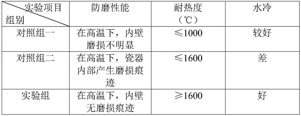
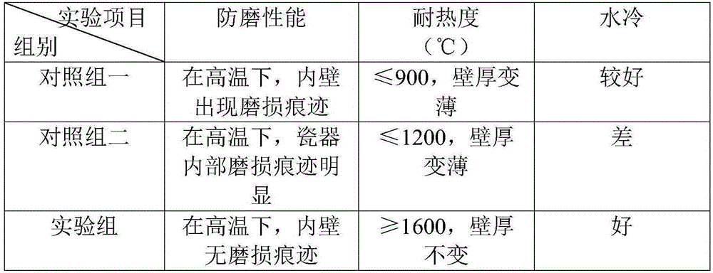

Embodiment 1

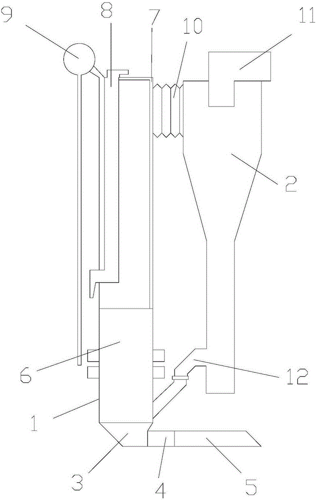
[0025] refer to figure 1 As shown, a power plant combustion boiler includes a furnace body 1 and a cyclone separator 2, the furnace body 1 includes an air distribution device 3, a combustion furnace 6 and a steam drum 9, and the air distribution device 3 is located below the combustion furnace 6 , the air distribution device 3 includes an igniter 4 and an air pipe 5, the igniter 4 and the air pipe 5 are connected, the combustion furnace 6 is provided with a water wall 7 and a filter 8, and the water wall 7 is located at Above the combustion furnace 6, the filter 8 is located at the upper left end of the water wall 7, the steam drum 9 is located at the upper left side of the combustion furnace 6, the steam drum 9 is connected with the water wall 7, and the cyclone separator 2 Located on the right side of the furnace body 1, the cyclone separator 2 includes an expansion pipe 10, a dust filter 11 and a return pipe 12, and the expansion pipe 10 is located on the upper right side o...

Embodiment 2

[0041] refer to figure 1 As shown, a power plant combustion boiler includes a furnace body 1 and a cyclone separator 2, the furnace body 1 includes an air distribution device 3, a combustion furnace 6 and a steam drum 9, and the air distribution device 3 is located below the combustion furnace 6 , the air distribution device 3 includes an igniter 4 and an air pipe 5, the igniter 4 and the air pipe 5 are connected, the combustion furnace 6 is provided with a water wall 7 and a filter 8, and the water wall 7 is located at Above the combustion furnace 6, the filter 8 is located at the upper left end of the water wall 7, the steam drum 9 is located at the upper left side of the combustion furnace 6, the steam drum 9 is connected with the water wall 7, and the cyclone separator 2 Located on the right side of the furnace body 1, the cyclone separator 2 includes an expansion pipe 10, a dust filter 11 and a return pipe 12, and the expansion pipe 10 is located on the upper right side o...

Embodiment 3

[0057] refer to figure 1 As shown, a power plant combustion boiler includes a furnace body 1 and a cyclone separator 2, the furnace body 1 includes an air distribution device 3, a combustion furnace 6 and a steam drum 9, and the air distribution device 3 is located below the combustion furnace 6 , the air distribution device 3 includes an igniter 4 and an air pipe 5, the igniter 4 and the air pipe 5 are connected, the combustion furnace 6 is provided with a water wall 7 and a filter 8, and the water wall 7 is located at Above the combustion furnace 6, the filter 8 is located at the upper left end of the water wall 7, the steam drum 9 is located at the upper left side of the combustion furnace 6, the steam drum 9 is connected with the water wall 7, and the cyclone separator 2 Located on the right side of the furnace body 1, the cyclone separator 2 includes an expansion pipe 10, a dust filter 11 and a return pipe 12, and the expansion pipe 10 is located on the upper right side o...


PUM


Abstract

The invention discloses a combustion boiler of a power station. The combustion boiler comprises a furnace body and a cyclone separator, wherein the furnace body comprises a wind distribution device, a combustion furnace and a steam dome; the wind distribution device is located below the combustion furnace; the wind distribution device comprises an igniter and an air pipe; the igniter is connected with the air pipe; a water cooling wall and a filter are arranged on the combustion furnace; the water cooling wall is arranged on the combustion furnace; the filter is located on the left upper end of the water cooling wall; the steam dome is located on the left upper side of the combustion furnace; the steam dome is connected with the water cooling wall; the cyclone separator is located on the right side of the furnace body; the cyclone separator comprises an expansion pipeline, a smoke filter and a material return pipe; the expansion pipeline is located on the right upper side of the cyclone separator, and is connected with the furnace body; the smoke filter is arranged on the cyclone separator; and the material return pipe is located below the cyclone separator. The combustion boiler of the power station has the advantages that fuels can be fully combusted; the utilization efficiency is improved; the energy is saved; and the environment is protected.

Description

technical field [0001] The invention belongs to the field of electric equipment, and in particular relates to a combustion boiler for a power station. Background technique [0002] Flame detectors are installed inside the boiler furnace, and its function is to detect the combustion situation in the furnace in real time. Once an abnormal situation occurs, the boiler door will be automatically closed through the relevant control device, and the boiler will be shut down. During the use of the boiler, coking is a relatively common phenomenon in the operation of coal-fired boilers. It will destroy the normal combustion conditions, reduce boiler output, and disrupt normal water circulation and other undesirable phenomena. In severe cases, large coke pieces of the boiler will fall in the cold After entering the slag hopper, a large amount of water vapor is generated instantaneously, causing negative pressure fluctuations in the furnace. When this phenomenon occurs, the flame detect...

Claims


Application Information

Patent Timeline
Patent Type & Authority Applications(China)
IPC IPC(8): F22B31/00F22B37/10C22C29/00C22C32/00
CPCC22C47/08C22C49/08C22C49/14F22B1/22F22B31/00F23J15/027F23J2217/10F23M5/08
Inventor 李聪
Owner 江苏橙果能源环保有限公司
Learn More