Optical comb system for implementing wideband carrier enveloped offset frequency control with electro-optic crystal

An electro-optic crystal and broadband carrier technology, applied in circuits, lasers, electrical components, etc., can solve problems such as limiting optical comb power, AOM power loss, and narrow working range, so as to improve system control accuracy, reduce high-frequency noise, and improve The effect of control precision

Active Publication Date: 2016-01-13
NAT TIME SERVICE CENT CHINESE ACAD OF SCI
View PDF6 Cites 13 Cited by
  • Summary
  • Abstract
  • Description
  • Claims
  • Application Information

AI Technical Summary

Problems solved by technology

However, f ceo There have been few breakthroughs in the control technology. Some scientists have used the post-compensation method to optically shift the optical frequency of the optical comb signal by using the acousto-optic modulator (AOM), but the control bandwidth still has not reached the order of megahertz.
Moreover, both f ceo There are obvious flaws in the control methods
By controlling the pump current through broadband, because the current is large, the corresponding broadband noise level is also high, and more noise will inevitably be introduced while increasing the control bandwidth; on the one hand, AOM’s The damage threshold limits the comb power, and AOM introduces some power loss
On the other hand, after the laser passes through the AOM, optical components related to the modulation frequency will be introduced. These redundant spectral components may affect the later application of the optical comb.
In addition, the optimal operating frequency of AOM is fixed, and the operating range is very narrow, making its effect on f ceo The control range of the signal is very limited

Method used


Image

  • Optical comb system for implementing wideband carrier enveloped offset frequency control with electro-optic crystal
  • Optical comb system for implementing wideband carrier enveloped offset frequency control with electro-optic crystal
  • Optical comb system for implementing wideband carrier enveloped offset frequency control with electro-optic crystal

Examples


Embodiment Construction

[0026] The present invention will be further described below in conjunction with the accompanying drawings and embodiments, and the present invention includes but not limited to the following embodiments.

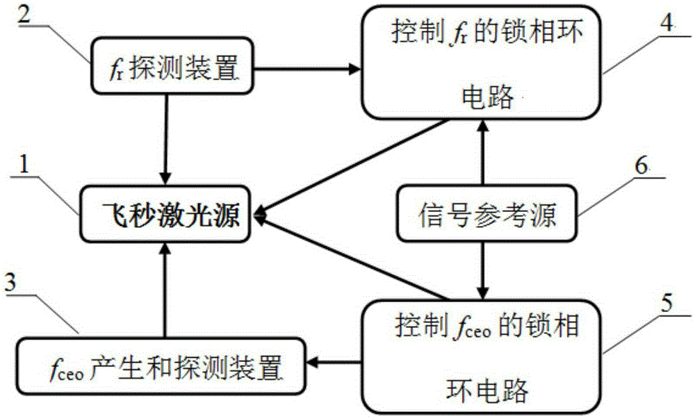
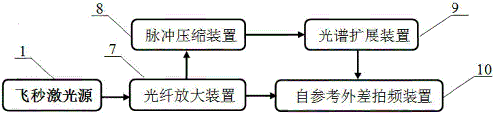
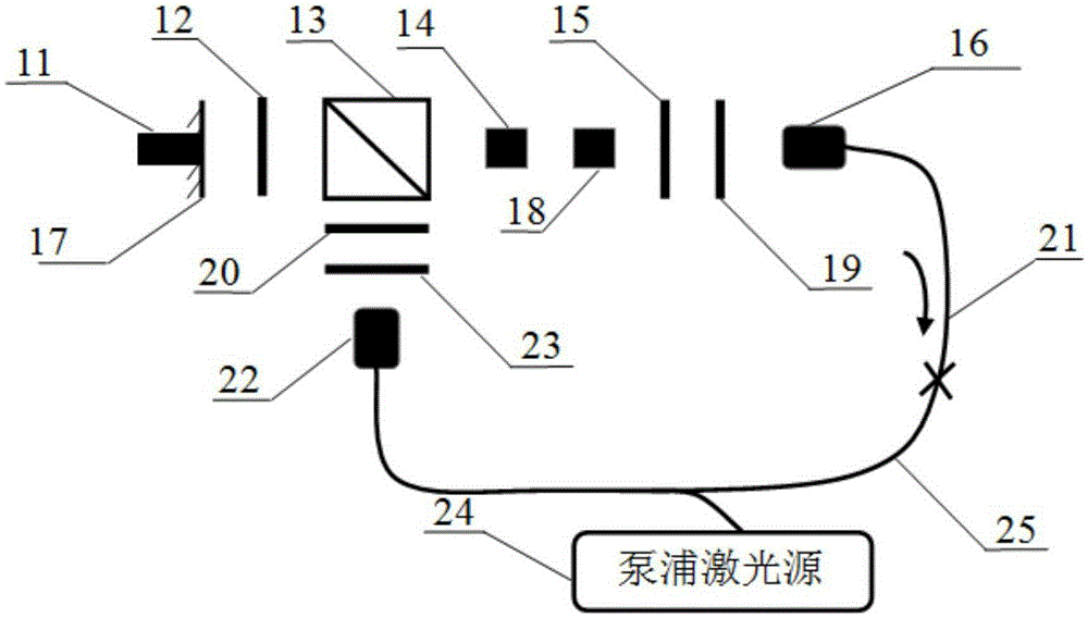
[0027] The present invention proposes a method for controlling laser polarization in an optical cavity by utilizing crystal electro-optic effect, and realizes f ceo Optical comb system for broadband frequency control. First, due to the fast response of the electro-optic effect, f ceo , and its control bandwidth reaches the order of megahertz; secondly, this method can avoid the defects of the two broadband control methods in the prior art. The cost of this approach is the same as f r The control is the same, is to add a specially designed electro-optic crystal in the optical cavity, and the adverse parasitic effects introduced by it can basically be ignored. The present invention is applicable to an optical comb system based on a nonlinear polarization rotation mode-lock...


PUM


Abstract

The invention provides an optical comb system for implementing wideband carrier enveloped offset frequency control with electro-optic crystal. After femtosecond pulse generated by a femtosecond laser source is coupled into an optical fiber by an optical fiber coupler, the output power is divided into three portions by an optical fiber beam splitter, wherein one portion is transmitted to an fr detection device to obtain an fr signal, the other portion enters an fceo generation and detection device to obtain an fceo signal, and another portion is used as the output of the optical comb system; the fr signal and the fceo signal are respectively mixed with an external reference signal and then output to a corresponding phase-locked loop circuit, fr and fceo feedback control signals are respectively obtained by phase discrimination and proportional integral processing, and then the femtosecond laser source is driven by the fr and fceo feedback control signals to lock fr and fceo to a stable external reference source. The optical comb system can realize wideband locking of an optical comb fceo, so that the control bandwidth of fceo reaches the magnitude of megahertz, and then a high-precision optical comb system is obtained.

Description

technical field [0001] The invention relates to a frequency control technology of an optical comb, which uses crystal electro-optic effect to control the laser polarization state, realizes rapid control of the carrier envelope frequency deviation of the optical comb, can effectively improve the frequency control bandwidth, and further improves the frequency control accuracy of the optical comb system. Background technique [0002] Optical comb, also known as "optical frequency synthesizer", is a fully frequency-controlled mode-locked laser, which can realize high-precision frequency conversion from optical frequency to microwave frequency (or other optical frequency). Since the invention of the optical comb at the end of the last century, it has played an important role in many research fields such as optical frequency standard research, high-precision optical frequency transmission, lidar development, ultra-stable microwave signal generation, and precision spectroscopy. [...

Claims


Application Information

Patent Timeline
Patent Type & Authority Applications(China)
IPC IPC(8): H01S3/098H01S3/106
Inventor 张颜艳姜海峰张龙闫露露赵文宇张首刚
Owner NAT TIME SERVICE CENT CHINESE ACAD OF SCI
Why Eureka
Try Eureka