Machine tool hydraulic pressure station

A hydraulic station and machine tool technology, which is applied in the direction of mechanical equipment, fluid pressure actuation devices, fluid pressure actuation system components, etc., can solve problems such as aging of hydraulic station parts and pipelines, reduction of hydraulic oil quality, and unstable hydraulic pressure. Achieve the effects of reducing workpiece deformation, reducing consumption, and stabilizing pressure

Inactive Publication Date: 2016-01-20
CHINA NTAIONAL NUCLEAR TIANJIN MACHINERY
View PDF7 Cites 3 Cited by
  • Summary
  • Abstract
  • Description
  • Claims
  • Application Information

AI Technical Summary

Problems solved by technology

[0002] With the increase of output, after a long period of full-load operation, it is found that the hydraulic station of the machine tool has problems of varying degrees, such as the oil suction port and the inner wall of the oil tank cannot be cleaned, which reduces the quality of hydraulic oil and increases the wear of the inner wall. jam
Frequent oil leakage in the oil tank causes excessive consumption of hydraulic oil, resulting in waste
The parts and pipes of the hydraulic station are seriously aging, resulting in unstable hydraulic pressure, unable to output the pressure required for processing, which can easily cause the clamping force of the chuck to be unstable and deform the workpiece, and there is a safety hazard of the workpiece flying out

Method used


Image

  • Machine tool hydraulic pressure station
  • Machine tool hydraulic pressure station

Examples


Embodiment Construction

[0029] The machine tool hydraulic station of the present invention will be described in detail below in conjunction with the drawings and embodiments of the description:

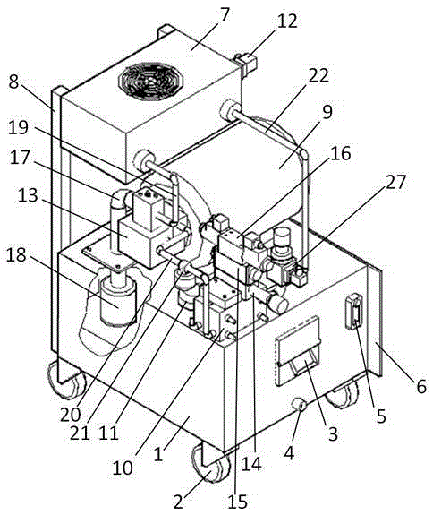
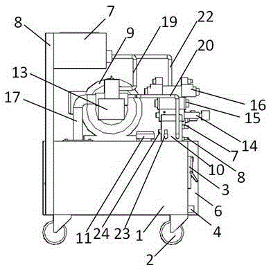
[0030] Such as figure 1 , 2 As shown, a machine tool hydraulic station includes a fuel tank 1 and a radiator 7. A three-phase asynchronous motor 9 and a valve block 10 are installed on the upper surface of the fuel tank 1, and the valve block 10 communicates with the fuel tank 1; the three-phase asynchronous motor 9- A variable displacement pump 13 is installed on the side wall, a pressure reducing valve 14 and a pressure relay 27 are installed above the valve block 10, and a pressure maintaining valve 15 and a solenoid valve 16 are installed on the top of the pressure reducing valve 14 from bottom to top; The pipe 17 communicates with the oil suction port filter 18 arranged inside the oil tank 1, and the other end communicates with the radiator 7 and the valve block 10 through the radiator oil inlet pipe 1...


PUM


Abstract

The invention discloses a machine tool hydraulic pressure station which comprises an oil tank and a radiator, wherein a three-phase asynchronous motor and a valve block are mounted on the upper top surface of the oil tank; a variable pump is mounted on one side wall of the three-phase asynchronous motor; a pressure reducing valve, a pressure retaining valve and a solenoid valve are mounted above the valve block from bottom to top in sequence; one end of the variable pump communicates with an oil suction opening filter arranged inside the oil tank through an oil suction tube; the other end of the variable pump communicates with the radiator and the valve block through a radiator oil inlet tube and a main pressure tube; the radiator communicates with the oil tank through a radiator oil return tube; and a knife tower oil port A, a knife tower oil port B, a chuck oil port A and a chuck oil port B are arranged on the side wall of the valve block. According to the machine tool hydraulic pressure station, pressure stability is guaranteed, workpiece deformation caused by pressure stability is reduced, processing safety of equipment is guaranteed, and guarantee is provided for increasing first-pass yield of workpieces; and meanwhile, consumption of hydraulic oil is reduced and waste is reduced.

Description

technical field [0001] The invention belongs to a hydraulic device, in particular to a machine tool hydraulic station. Background technique [0002] With the increase of output, after a long period of full-load operation, it is found that the hydraulic station of the machine tool has problems of varying degrees, such as the oil suction port and the inner wall of the oil tank cannot be cleaned, which reduces the quality of hydraulic oil and increases the wear of the inner wall. clogged. Frequent oil leakage in the oil tank causes excessive consumption of hydraulic oil and waste. The parts and pipes of the hydraulic station are seriously aging, resulting in unstable hydraulic pressure, unable to output the pressure required for processing, which can easily cause the clamping force of the chuck to be unstable and deform the workpiece, and there is a safety hazard of the workpiece flying out. Contents of the invention [0003] The present invention is proposed in order to ov...

Claims


Application Information

Patent Timeline
Patent Type & Authority Applications(China)
IPC IPC(8): F15B11/08F15B21/04
Inventor 朱建帅张旸军延志鹏张洋杨磊李宏君昝亚娜李彬王超李力
Owner CHINA NTAIONAL NUCLEAR TIANJIN MACHINERY
Why Eureka
Try Eureka