Measuring device, measuring system and measuring method of continuous metering gas flow meter

The technology of a gas flowmeter and measurement method is applied in the direction of measuring device, liquid/fluid solid measurement, test/calibration device, etc., which can solve the problems of long measurement test time, not wide detection range, and reduced work efficiency, so as to achieve convenient Effect of control and operation, wide detection range, and improvement of work efficiency

Active Publication Date: 2019-07-23
WUHAN HAIWANG MECHANICAL & ELECTRICAL ENGTECH
View PDF4 Cites 0 Cited by
  • Summary
  • Abstract
  • Description
  • Claims
  • Application Information

AI Technical Summary

Problems solved by technology

When the metering flow rate is at the lower limit of the range of the standard device, the time for the metering test is too long, and the detection range of the traditional gas flow standard device is often not wide, and the range is very small, resulting in reduced work efficiency and increased cost

Method used


Image

  • Measuring device, measuring system and measuring method of continuous metering gas flow meter
  • Measuring device, measuring system and measuring method of continuous metering gas flow meter
  • Measuring device, measuring system and measuring method of continuous metering gas flow meter

Examples


Embodiment 1

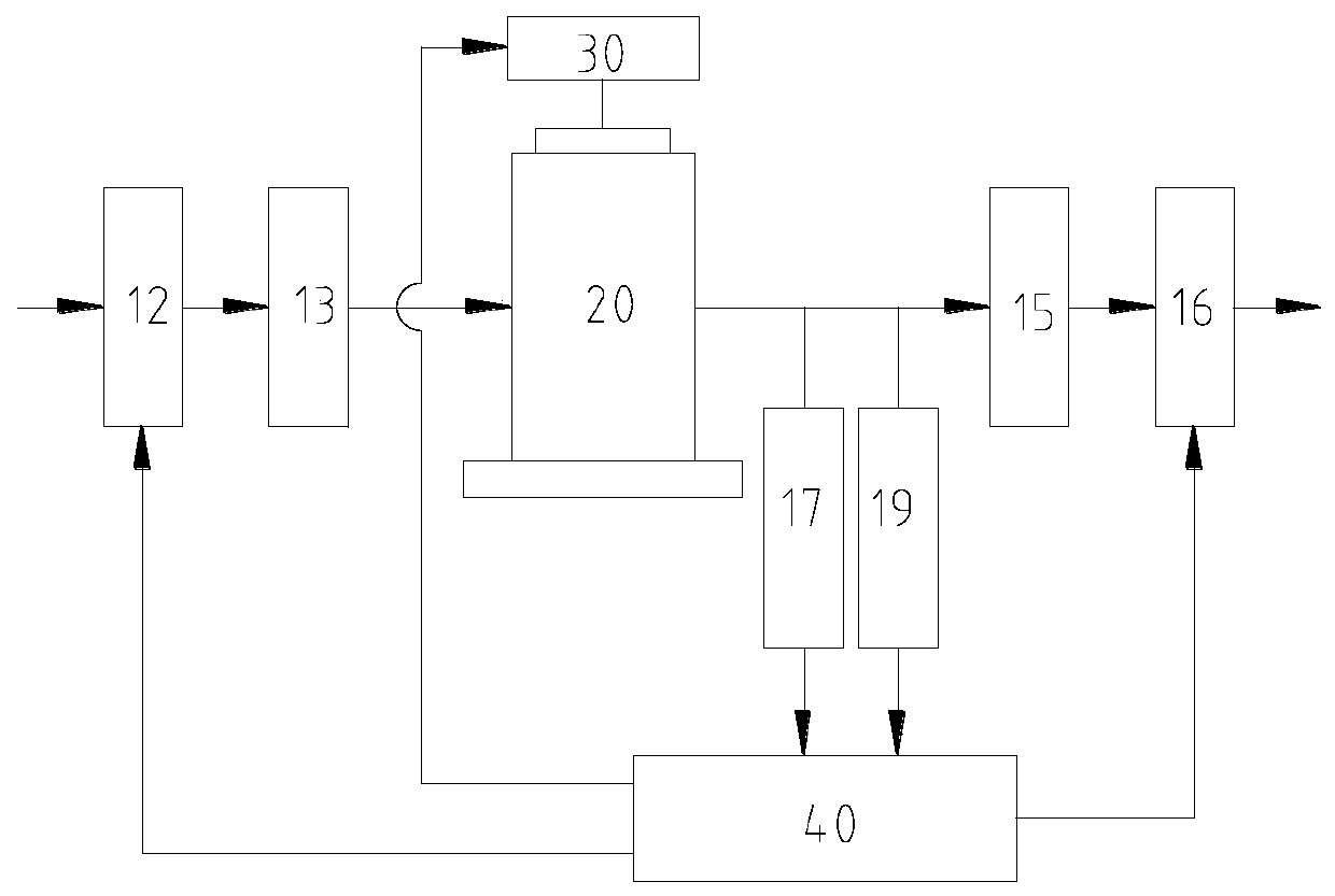
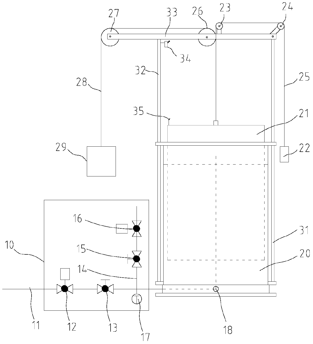
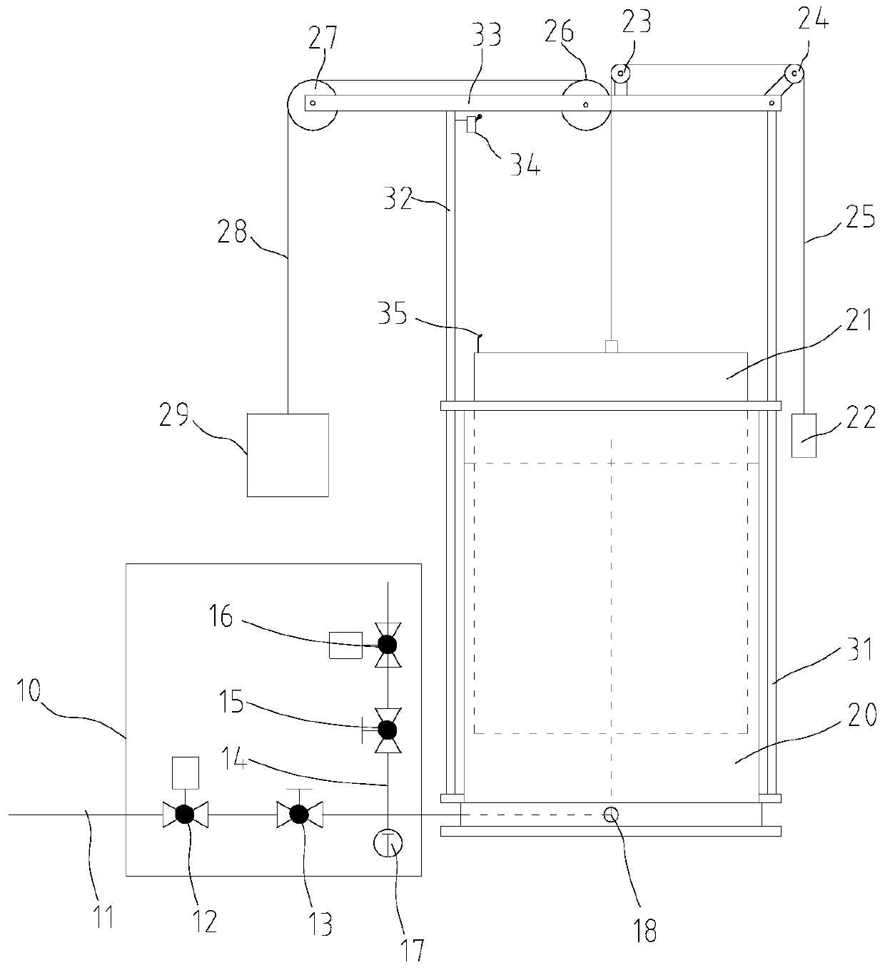
[0056] see figure 1 and figure 2 As shown, the embodiment of the present invention provides a measuring device for continuous metering gas flow meter, including

[0057] A metering cylinder 20, the measuring cylinder 20 is in the shape of a cylinder with an open upper end, the measuring cylinder 20 is provided with a sealing liquid and a buoy 21, the buoy 21 is in the shape of a cylinder with an outer diameter slightly smaller than the inner diameter of the measuring cylinder 20, and the water level of the buoy 21 is The open end is immersed in the sealing liquid;

[0058] A pipeline system 10, which includes an air inlet pipe 11 and an air outlet pipe 14, one end of the air inlet pipe 11 is connected to the output end of the measured flowmeter, and the other end enters the inside of the metering cylinder 20 from the side wall near the bottom of the metering cylinder 20, and The sealing liquid extends upwards into the buoy 21 in a bent shape, and gas is introduced into the ...

Embodiment 2

[0084] The difference between embodiment 2 and embodiment 1 is that structurally embodiment 2 also includes a travel switch 34 and a baffle plate 35, the travel switch 34 is arranged on the upper part of the left column 32, and the upper end of the buoy 21 is arranged at the relative position of the left column 32. The baffle plate 35, the baffle plate 35 is used in conjunction with the travel switch 34, and the travel switch 34 is connected to the computing device 40 for signals;

[0085] The specific differences in the measurement methods are:

[0086] Among the specific detection steps in embodiment 1:

[0087] 1) Pre-detection gas volume Q is set in computing device 40 0 and detection gas volume Q 1 ;

[0088] 6) End of detection: when the gas volume V in the metering cylinder 20 1 When the detected gas volume Q1 in the calculation device 40 is reached, the calculation device 40 controls the intake solenoid valve 12 to close, manually closes the intake ball valve 13 to s...

Embodiment 3

[0093] The difference between Embodiment 3 and Embodiment 1 is that the real-time displacement measuring device is a capacitive displacement sensor installed on the upper beam 33 to detect the displacement of the buoy 21 in real time.


PUM


Abstract

The invention discloses a measurement device for a continuous measurement gas flow meter. The measurement device comprises a measuring cylinder, a pipeline system, a balance assembly, a temperature detecting device, a pressure detecting device and a real-time displacement measuring device. Sealing liquid and a floating cylinder are arranged in the measuring cylinder, and a lower end opening of the floating cylinder is steeped in the sealing liquid. The pipeline system stretches into the measuring cylinder and is communicated with the floating cylinder. The balance assembly comprises a pulley, a pull rope, a chain wheel and a chain, wherein one end of the pull rope is connected with the top of the floating cylinder, and the other end of the pull rope is wound around the pulley and connected with a first weight; one end of the chain is connected with the top of the floating cylinder, the other end of the chain is wound around the chain wheel and connected with a second weight, the sum of the gravity of the first weight and the gravity of the second weight is equal to the gravity of the floating cylinder, and the first weight and the second weight are used for balancing the gravity of the floating cylinder. The temperature detecting device is used for detecting the temperature of gas in the floating cylinder in real time. The pressure detecting device is used for detecting the pressure of the gas in the floating cylinder in real time. The real-time displacement measuring device is used for measuring the height of the part, in the measuring cylinder, of the floating cylinder in real time. The same accuracy is achieved with the full measuring range, and the measurement device is simple in structure and wide in measurement range.

Description

technical field [0001] The invention relates to the field of metering and testing, in particular to a measuring device, a measuring system and a measuring method of a continuous metering gas flowmeter. Background technique [0002] The gas flow standard device is the value transmission standard of the gas flow in a closed pipeline, which can be used for the verification and calibration of various types of gas flow meters, as well as the research of gas flow measurement verification and test methods. [0003] In order to improve the detection accuracy, the traditional gas flow standard device usually only measures the small length of the measuring cylinder inlet, and does not measure the large length of the measuring cylinder body. When the metering flow is at the lower limit of the range of the standard device, the time for the metering test is too long, and the detection range of the traditional gas flow standard device is often not wide, and the range is very small, result...

Claims


Application Information

Patent Timeline
Patent Type & Authority Patents(China)
IPC IPC(8): G01F25/00
Inventor 胡火焰刘刚曾嵘齐军唐顺杰蔡天舒刘洋刘亮王军杨诚罗友高戴青傅捷王震周梓丞
Owner WUHAN HAIWANG MECHANICAL & ELECTRICAL ENGTECH
Why Eureka
Try Eureka