Contrast test method for improving fretting fatigue resistance performance of material by laser shot blasting strengthening and test sample clamping device
A technology of laser shot peening and fretting fatigue, which is used in the application of repetitive force/pulsation force to test the strength of materials and the preparation of samples for testing.
- Summary
- Abstract
- Description
- Claims
- Application Information
AI Technical Summary
Problems solved by technology
Method used
Image

Examples
Embodiment 1
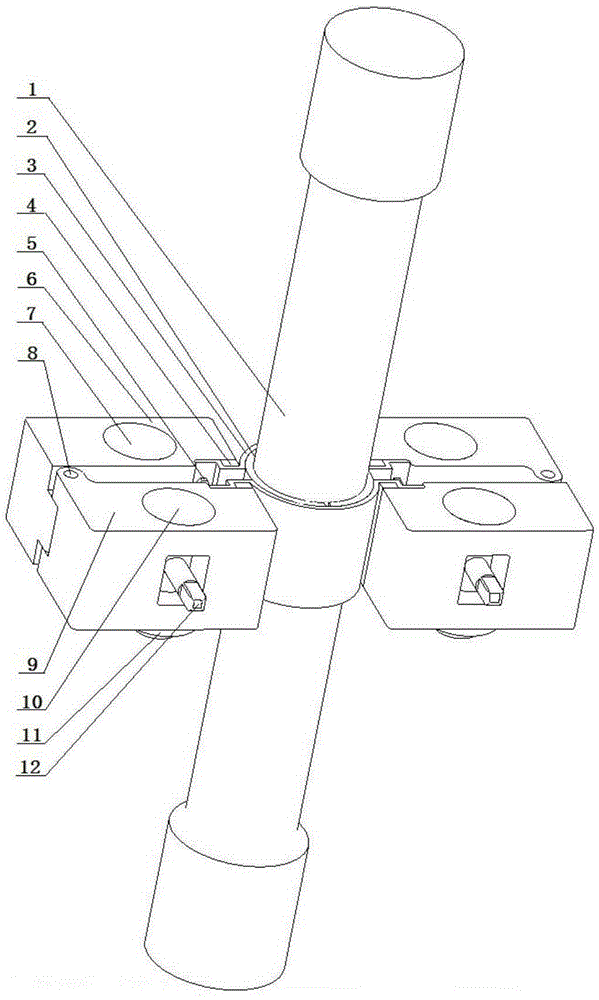
[0040] Such as Figure 1-5 shown.
[0041] A comparative test method for improving the anti-fretting fatigue performance of materials by laser shot peening, the specific steps of which are as follows:
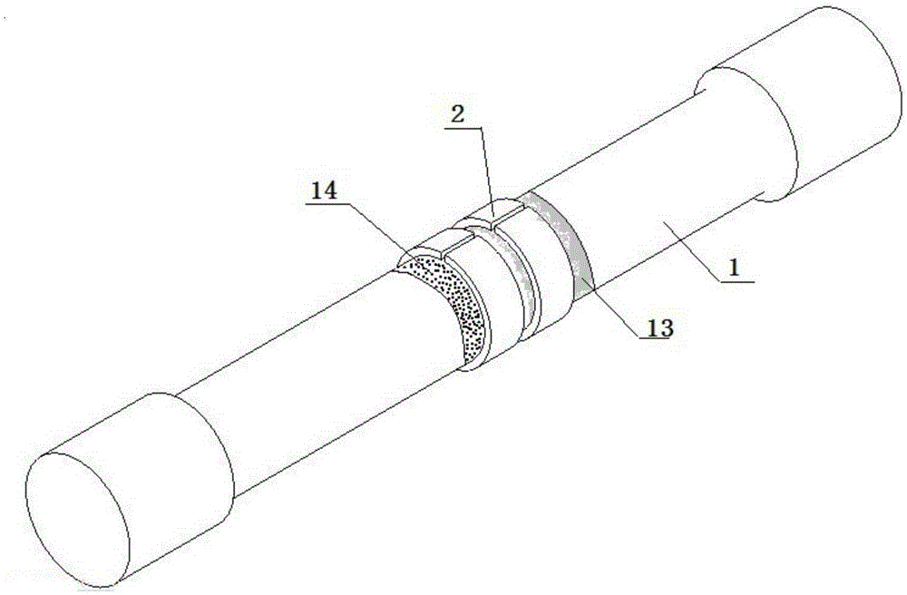
[0042] 1) Perform laser shot peening strengthening treatment on the entire circumference side area of the round bar sample 1 to be tested to form a strengthening shot peening area 13. As a test comparison, an area without surface treatment is reserved at its axially adjacent position as a test comparison Area 14, such as image 3 shown;
[0043] 2) if figure 2 As shown, the micro-movement pads 2 are respectively arranged in the two test areas, and the radius of the inner arc is equal to the radius of the round bar sample 1. Four semi-circular surface micro-motion pads fit and surround the two test areas. The axial distance between the fretting pads is 5~10mm;
[0044] 3) The pressing metal sheet 3 is closely attached to the semi-circular surface micro-movement pad 2, an...
Embodiment 2
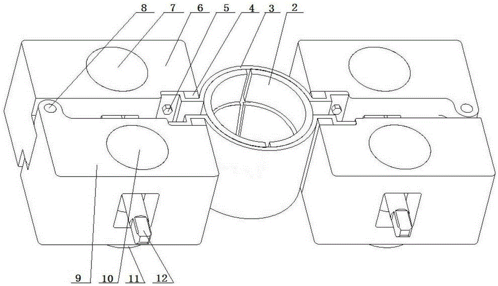
[0052] Such as Figure 1-3 shown.
[0053] A sample clamping device for laser shot peening to improve the comparative test of material fretting fatigue resistance performance, such as figure 2 As shown, it includes: it includes semi-circular surface fretting pad 2, pressing metal sheet 3, force measuring element 4, screw 5, main clamping block 6, main tensioning pin 7, pin 8, auxiliary clamping block 9. Auxiliary tightening pin 10, positioning gasket 11 and threaded rod 12, one group of two sets of semi-circular surface fretting pads 2 is closely attached to the laser peening area 13 on the surface of the round bar sample 1, and the other group is tightly attached to the surface of the round bar sample 1. Pasted on the test contrast area 14 (such as image 3 ), the distance between the two sets of semi-annular micro-movement pads 2 is 5~10mm, two semi-annular compression metal sheets 3 are misplaced and mounted on two sets of semi-annular surface micro-movement pads 2, and ...
PUM
| Property | Measurement | Unit |
|---|---|---|
| Spot diameter | aaaaa | aaaaa |
| Thickness | aaaaa | aaaaa |
| Width | aaaaa | aaaaa |
Abstract
Description
Claims
Application Information
 - R&D
- Intellectual Property
- Life Sciences
- Materials
- Tech Scout
- Unparalleled Data Quality
- Higher Quality Content
- 60% Fewer Hallucinations
Browse by: Latest US Patents, China's latest patents, Technical Efficacy Thesaurus, Application Domain, Technology Topic, Popular Technical Reports.
© 2025 PatSnap. All rights reserved.Legal|Privacy policy|Modern Slavery Act Transparency Statement|Sitemap|About US| Contact US: help@patsnap.com