Active microstrip reflective array unit and microstrip reflective array antenna

A reflectarray antenna and reflectarray technology, which is applied to antennas, electrical components, circuits, etc., can solve the problems of inability to realize multi-beam scanning and beam pointing, and achieve good large-angle beam scanning performance, simple structure, and improved performance. The effect of stability

Inactive Publication Date: 2016-01-20
NAT SPACE SCI CENT CAS
View PDF3 Cites 6 Cited by
  • Summary
  • Abstract
  • Description
  • Claims
  • Application Information

AI Technical Summary

Problems solved by technology

However, the above four methods of phase compensation can only achieve fixed beam pointing, and cannot achieve multi-beam scanning function, because once the phase delay line length, patch size, rotation angle, and slit length loaded on the microstrip patch are determined After that, the phase th

Method used


Image

  • Active microstrip reflective array unit and microstrip reflective array antenna
  • Active microstrip reflective array unit and microstrip reflective array antenna
  • Active microstrip reflective array unit and microstrip reflective array antenna

Examples


Embodiment 1

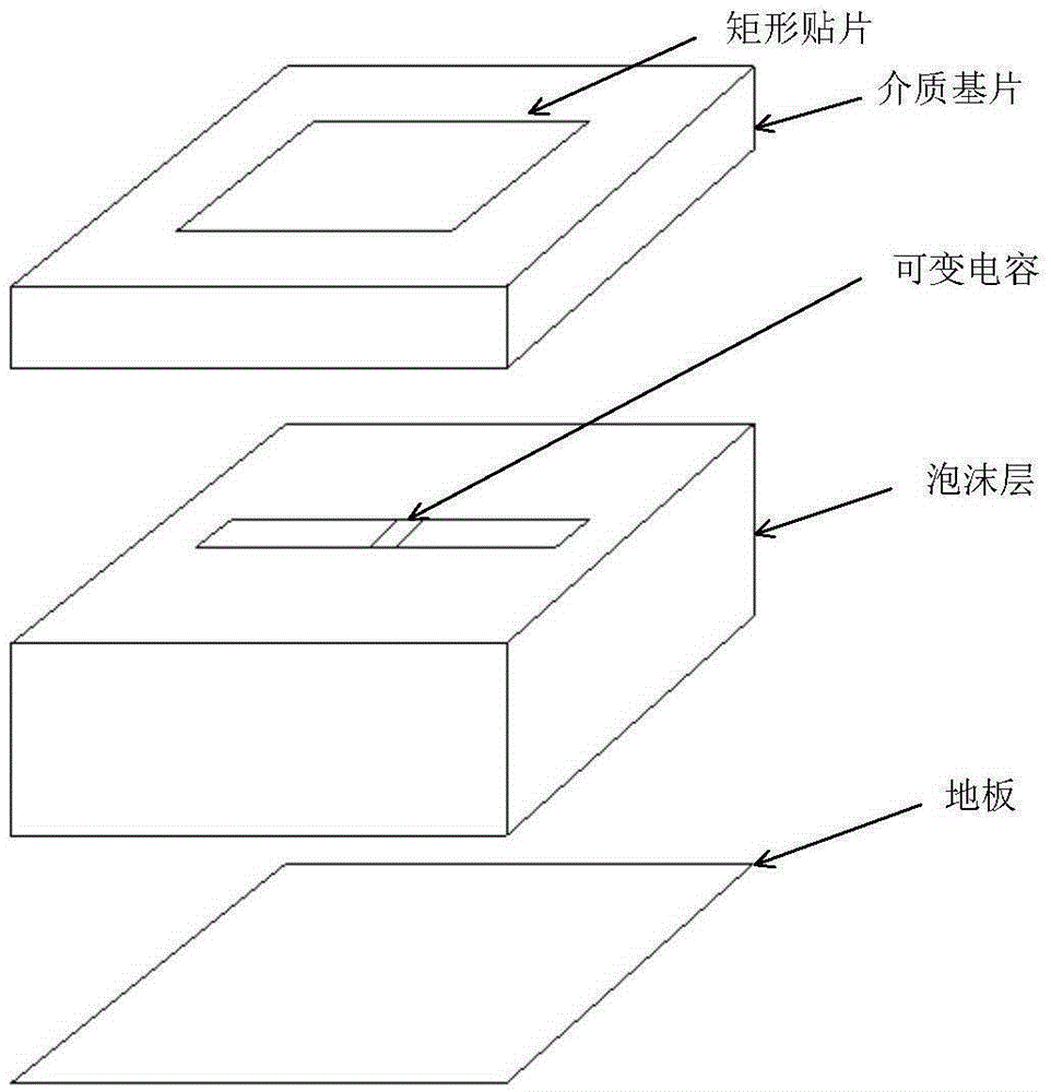
[0027] The slit length of the slotted floor loaded with variable capacitors equipped with the source microstrip reflectarray unit is Ls and the width is Ws; the selection of the slit length and width is based on the principle that the reflection phase curve has better linearity and a larger range; In this embodiment, when the operating frequency is 13.58 GHz, Ls=9mm and Ws=1mm are obtained through parameter optimization.

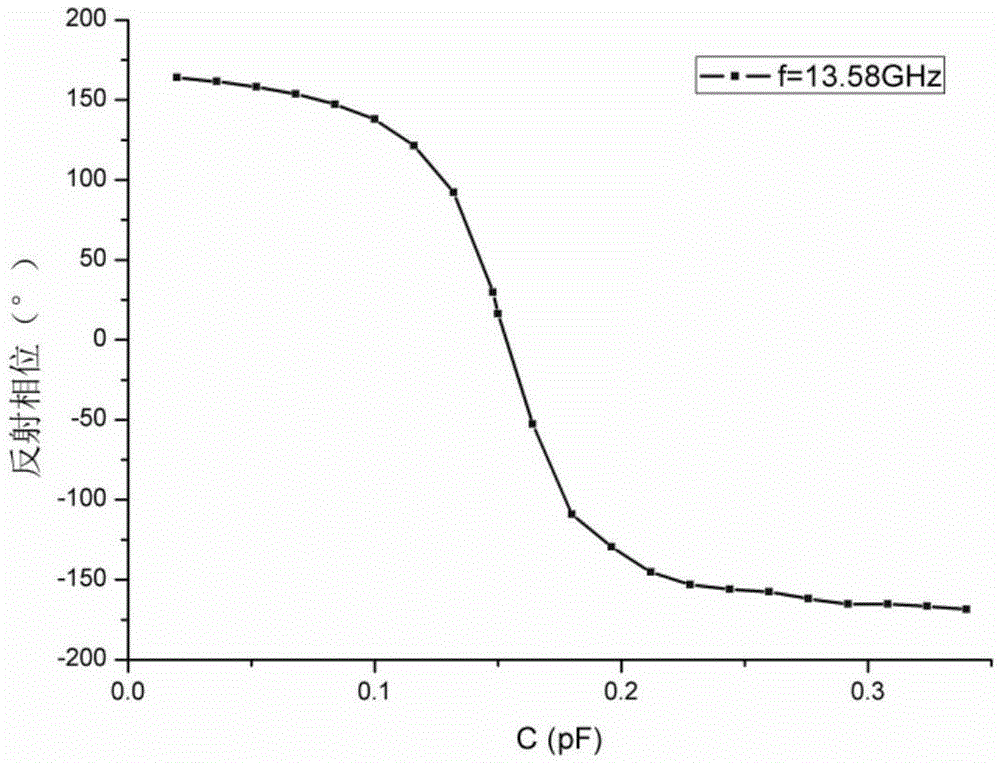
[0028] In the high-frequency electromagnetic simulation software HFSS, the phase shift characteristics of the active microstrip reflectarray unit are simulated and analyzed. The variable capacitor can use the lumped RLC boundary in HFSS, and the capacitance value is set to the variable C to replace it equivalently. Variable capacitance. The curve of the reflection phase of the unit changing with the capacitance value C is obtained by scanning the parameters of the variable C, which means that the reflection phase of the unit can be adjusted by adjusting the ...

Embodiment 2

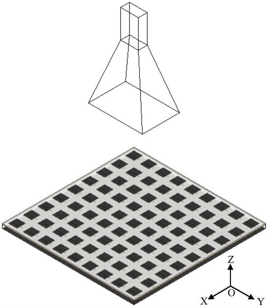
[0032] The reflectarray antenna of this embodiment includes a linearly polarized horn feed antenna with a polarization direction of X direction and a reconfigurable microstrip reflectarray; the center frequency of the reconfigurable microstrip reflectarray is 13.58GHz, and the size of the reflectarray is: 117mm*117mm, the feeding form of the antenna is positive feed, and the focal diameter ratio F / D=0.8. The phase center of the feed horn is placed at the focal point of the reflectarray antenna. Considering the aperture efficiency of the microstrip reflectarray antenna comprehensively, including aperture irradiation efficiency and interception efficiency, the size of the horn antenna is finally adjusted so that it is at the edge of the reflectarray aperture The edge illumination level is -11dB.

[0033] Through electromagnetic field propagation and array antenna theory, the phase value that needs to be compensated for each reflectarray unit in the specified beam direction can b...


PUM


Abstract

The invention provides an active microstrip reflective array unit. The unit comprises a rectangular patch, a dielectric substrate, a slotting floor loaded with a variable capacitor, a foam layer and a floor from top to bottom, wherein the slotting floor loaded with the variable capacitor is a metal plate opened with a slot, the variable capacitor is loaded at the middle of the slot, and the foam layer is a honeycomb flat plate made of foam material or paper. Further, the invention also provides a microstrip reflective array antenna. The antenna comprises a feeding source and a reconfigurable microstrip reflective array, wherein the feeding source is a pyramidal horn antenna, the reconfigurable microstrip reflective array comprises a plurality of active microstrip array units which are transversely, longitudinally and uniformly arranged, and the size of the slot of the slotting floor loaded with the variable capacitor of each active microstrip reflective array unit is same. The microstrip reflective array antenna provided by the invention has favorable wide-angle wave beam scanning performance, is relatively simple in structure, and has favorable performance.

Description

technical field [0001] The invention belongs to the technical field of antennas, in particular to an active microstrip reflection array unit and a microstrip reflection array antenna. Background technique [0002] In recent years, with the rapid development of aerospace technology, satellite communication and deep space exploration technology, more and more knowledge and research have been made on large-aperture high-gain antennas. Traditional high-gain antennas mainly include parabolic antennas or array antennas, but the two Both have shortcomings. The parabolic antenna itself is too bulky and heavy, and its special parabolic structure is difficult to process, and the scanning of the main beam of this type of antenna is realized by changing the position of the feed source, so its scanning range is very limited. Although the array antenna has a large scanning range, it requires a complex feed network and expensive T / R components, resulting in increased transmission loss, di...

Claims


Application Information

Patent Timeline
IPC IPC(8): H01Q3/46H01Q13/02H01Q15/14H01Q19/10
Inventor 薛飞王宏建
Owner NAT SPACE SCI CENT CAS
Why Eureka
Try Eureka