Integrated type current transformer device

A converter, integrated technology, applied in output power conversion devices, electrical components, cooling/ventilation/heating retrofits, etc. The effect of convenient equipment maintenance and repair, small cabinet space and equipment cost reduction

Inactive Publication Date: 2016-01-20
ZHUZHOU CSR TIMES ELECTRIC CO LTD
View PDF3 Cites 7 Cited by
  • Summary
  • Abstract
  • Description
  • Claims
  • Application Information

AI Technical Summary

Problems solved by technology

[0003] Part of the existing traction converters and auxiliary converters are mostly loaded in independent cabinets, which takes up a lot of space for the very limited installation space under the high-speed EMU; and the existing traction converters and auxiliary converters Most of the devices adopt air cooling, and the cooling power of air cooling is limited by the load capacity of the power supply. After the load power of the power supply increases to a certain capacity, the use of air cooling heat dissipation technology is limited; at the same time, from the perspective of the overall layout, the cooling air duct is from the side of the equipment The air enters and then passes through the internal air duct of the converter, and the air is discharged from the other side. The internal space planning of the equipment is limited, the cooling and circuit layout are difficult, the installation, disassembly and maintenance of components are inconvenient, the cooling efficiency is not high, and it also brings a certain vibration to the equipment noise problem
[0004] Although some existing traction auxiliary integrated converter devices also use water cooling methods, because the water cooling design adopts a series method, the design is single, and if one component of the series water cooling device fails, it will cause the entire cooling system to cool down. Reduced efficiency or even cooling failure, which will affect the safety of the train group

Method used


Image

  • Integrated type current transformer device
  • Integrated type current transformer device
  • Integrated type current transformer device

Examples


Embodiment Construction

[0027] The present invention will be described in further detail below in conjunction with specific embodiments and accompanying drawings.

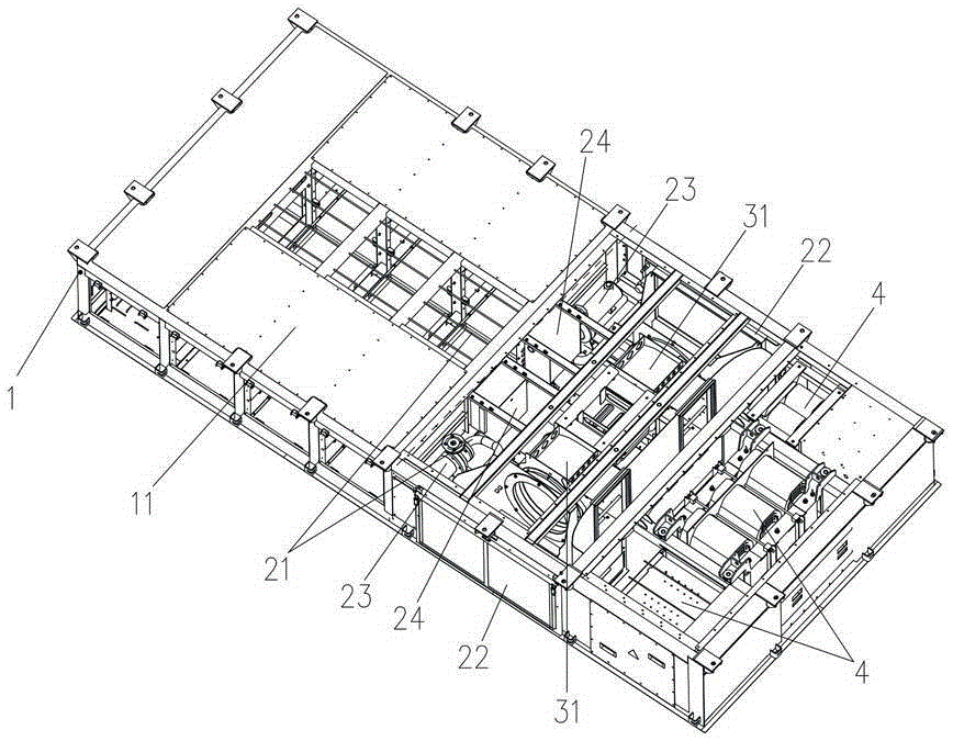
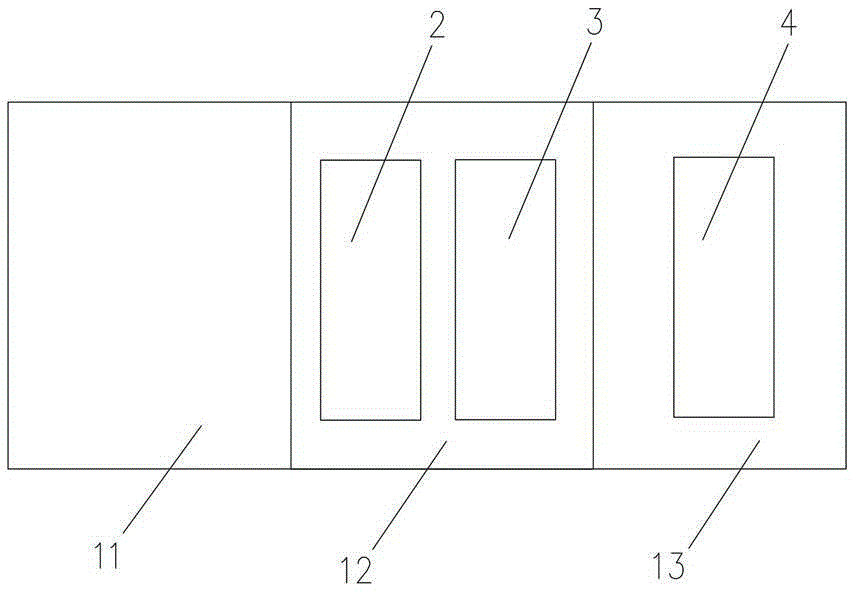
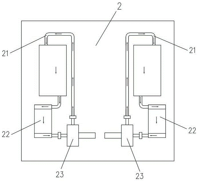
[0028] Such as Figure 1 to Figure 4 As shown, the present invention provides an integrated converter device, which includes a cabinet body 1. The cabinet body 1 includes a first cavity 11, a second cavity 12 and a third cavity 13 arranged horizontally in sequence. The first cavity 11 is equipped with traction converter modules and auxiliary converter modules (such as rectifier modules, inverter modules, auxiliary circuits, etc.), and the third cavity 13 is equipped with power unit modules 4 (such as transformers, reactors, resistors, etc. ), the second cavity 12 is provided with a water cooling module 2 for cooling modules in the first cavity 11 and an air cooling module 3 for cooling modules in the third cavity 13 . That is to say, the device integrates the traction converter and the auxiliary converter in the cabinet at the same time,...


PUM


Abstract

The invention discloses an integrated type current transformer device. The device comprises a cabinet body. The cabinet body comprises a first cavity body, a second cavity body and a third cavity body, which are successively horizontally arranged. A traction current transformer module and an auxiliary current transformer module are arranged in the first cavity body. A power unit module is arranged in the third cavity body. A water cooling module used for cooling modules in the first cavity body and a wind cooling module used for cooling the module in the third cavity body are arranged in the second cavity body. The device is advantaged by proper design, compact layout, high integration level and high heat dissipation efficiency.

Description

technical field [0001] The invention mainly relates to the field of rail transit equipment, and in particular to an integrated converter device. Background technique [0002] In applications such as high-speed EMUs or urban rail transit, it is necessary to use traction, auxiliary or traction auxiliary integrated converter devices for traction, braking control and auxiliary load power supply for trains. [0003] Part of the existing traction converters and auxiliary converters are mostly loaded in independent cabinets, which takes up a lot of space for the very limited installation space under the high-speed EMU; and the existing traction converters and auxiliary converters Most of the devices adopt air cooling, and the cooling power of air cooling is limited by the load capacity of the power supply. After the load power of the power supply increases to a certain capacity, the use of air cooling heat dissipation technology is limited; at the same time, from the perspective of...

Claims


Application Information

Patent Timeline
Patent Type & Authority Applications(China)
IPC IPC(8): H02M1/00H05K7/20
Inventor 荣智林李碧钰饶沛南李华李自然葛会军石东山谢海波彭希予
Owner ZHUZHOU CSR TIMES ELECTRIC CO LTD
Why Eureka
Try Eureka