
Phase-change heat exchanger and heat exchange method thereof

A phase change heat exchanger and heat method technology, which is applied in indirect heat exchangers, lighting and heating equipment, and greenhouse gas reduction, etc., can solve the problems of decreased heat transfer efficiency, scrapped heat exchangers, and high manufacturing and maintenance costs of heat pipes. , to achieve the effect of stable exhaust gas temperature and wall temperature, reducing flue gas emission temperature and avoiding corrosion phenomenon

Inactive Publication Date: 2016-01-27
JILIN ELECTRIC POWER RES INST +1
View PDF6 Cites 9 Cited by
  • Summary
  • Abstract
  • Description
  • Claims
  • Application Information

AI Technical Summary

Problems solved by technology

However, in the actual working process, the heat pipe heat exchanger is mainly assembled from multiple heat pipes, and there are manufacturing differences between them, and the positions are also different. Therefore, the wall temperature of the heat pipes is not completely consistent, and the temperature adjustment is difficult. Reduce the heat transfer performance of the heat pipe, and when the heat transfer efficiency drops sharply to a certain extent, the heat exchanger will be scrapped, and the manufacturing and maintenance costs of the heat pipe are huge

Method used


Image

  • Phase-change heat exchanger and heat exchange method thereof
  • Phase-change heat exchanger and heat exchange method thereof
  • Phase-change heat exchanger and heat exchange method thereof

Examples


specific Embodiment approach

[0037] In order to further illustrate the technical solution of the present invention, in conjunction with the accompanying drawings, the specific implementation of the present invention is as follows:

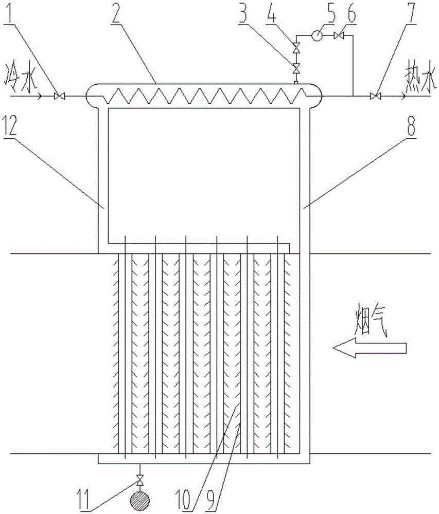
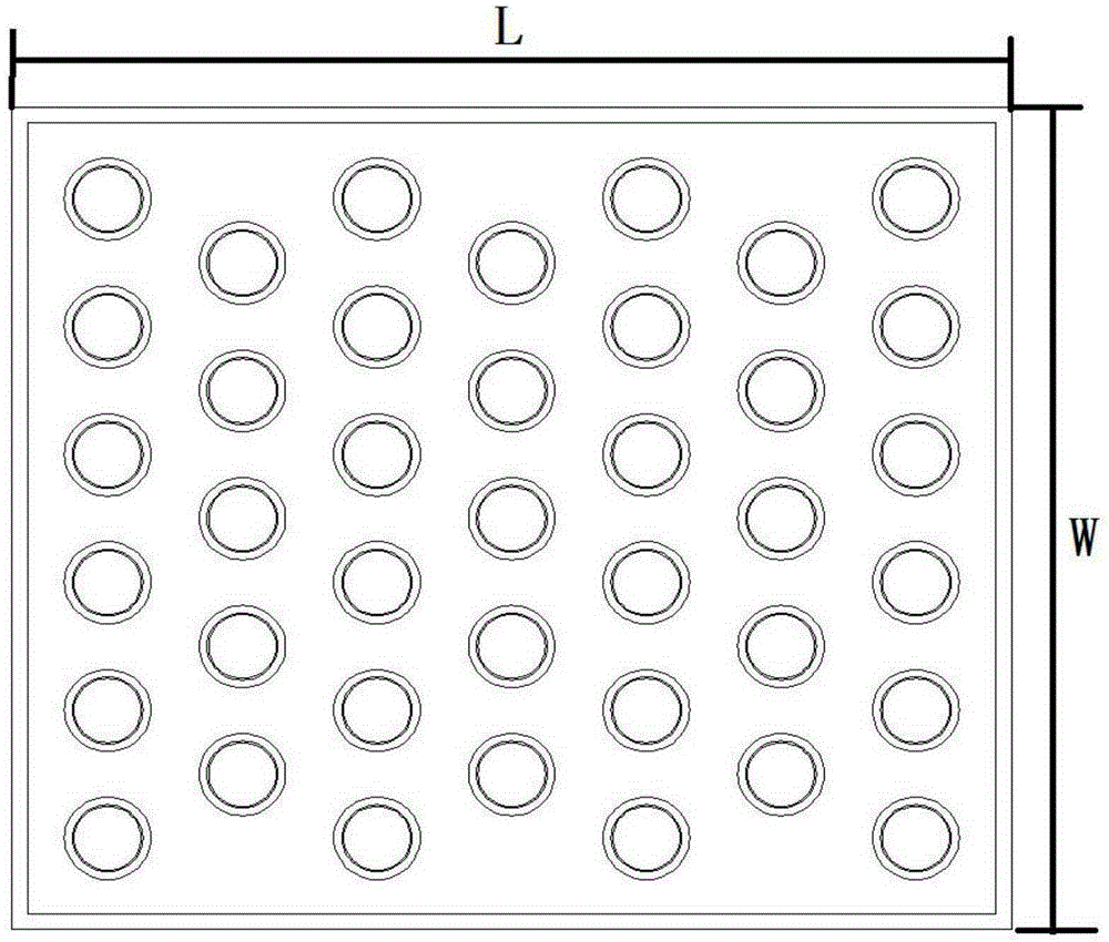
[0038] The heat transfer principle of the phase change heat exchanger provided by the present invention is similar to that of a heat pipe, and can be regarded as a large heat pipe. It is mainly composed of two parts: the evaporation chamber and the condensation chamber. A number of straight pipes are arranged in the evaporation chamber. The straight pipe is equipped with an intermediate cooling medium. The medium and low temperature flue gas flows through the area between the evaporation chamber and the straight pipe. The condensation chamber is equipped with a condensate pipe. 12. Multiple valves are set on the top of the condensation chamber. The specific structure of the phase change heat exchanger of the present invention is as follows:

[0039] Such as figure 1 As shown,...


PUM


Abstract

The invention discloses a phase-change heat exchanger and a heat exchange method thereof. The heat exchanger is composed of a condensation chamber above and an evaporation chamber below. A steam package is arranged in the condensation chamber, and a valve bank is arranged on the top of the condensation chamber and connected with the steam package so that closed-loop control can be carried out over the lowest temperature of a heated metal wall face in a system; a plurality of straight tubes are distributed in the evaporation chamber, the top end of the evaporation chamber is communicated with one end of the steam package through a condensation water pipe, the bottom end of the evaporation chamber is communicated with the other end of the steam package through a steam raising pipe, and a loop is formed between the condensation chamber and the evaporation chamber. The heat exchanger is matched with an economizer in a power station boiler to recycle smoke waste heat and carry out circulating phase-change heat exchange. By means of the phase-change heat exchanger and the heat exchange method thereof, smoke exhaust temperature can be greatly lowered, and meanwhile smoke waste heat is fully used. Besides, the temperature of the heated metal wall face is further kept on a high temperature level, so that the heated metal wall face is far away from a dew point corrosion area of acid. Thus, the corrosion phenomenon is avoided, and use reliability of equipment is improved.

Description

technical field [0001] The invention belongs to the field of thermal energy, and relates to a phase-change heat exchanger and a heat exchange method thereof which utilize flue gas waste heat recovery, and are mainly used as economizers in power plant boilers. Background technique [0002] At present, waste heat recovery from flue gas in power plant boilers has been extensively researched and utilized. The energy level of medium and low temperature waste heat is low, and the heat transfer efficiency is low. It is aimed at the development and utilization of waste heat of flue gas at medium and low temperature. [0003] For medium and low temperature flue gas waste heat, air preheaters and economizers are generally used to heat air and feed water, and can also be used to heat materials. First, the economizer mainly uses the heat absorbed by the low-temperature flue gas to reduce the exhaust gas temperature. Secondly, the feed water is first heated in the economizer, thereby re...

Claims


Application Information

Patent Timeline
IPC IPC(8): F28D15/02F23J15/06
CPCY02E20/30
Inventor 韩季廷刘炳刘秀石红蕾刘研
Owner JILIN ELECTRIC POWER RES INST
Learn More