Supercharge Your Innovation With Domain-Expert AI Agents!

Novel demister

A demister, a new type of technology, applied in chemical instruments and methods, separation methods, liquid degassing, etc., can solve the problems of difficulty in reaching the concentration of fog droplets and particulate matter at the exhaust port, and low removal efficiency of small particle size droplets. To achieve the effect of flexible use, novel structure design, and reduction of secondary entrainment

Active Publication Date: 2016-02-03
JIANGSU LANSHAN ENVIRONMENT TECH
View PDF8 Cites 8 Cited by
  • Summary
  • Abstract
  • Description
  • Claims
  • Application Information

AI Technical Summary

Problems solved by technology

[0003] In order to solve the problem that the existing purification equipment has low removal efficiency for small particle size droplets, and the concentration of fog droplets and particulate matter at the exhaust port is difficult to reach the standard, the present invention provides a new type of mist eliminator with high demisting efficiency

Method used


Image

  • Novel demister
  • Novel demister
  • Novel demister

Examples


Embodiment 1

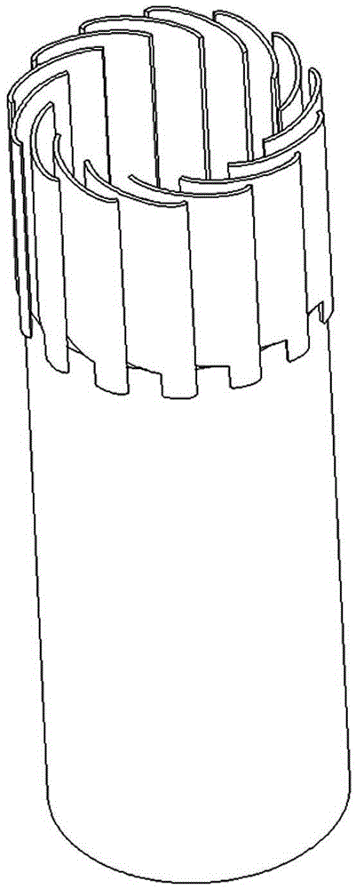
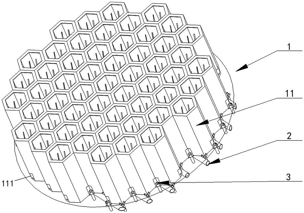
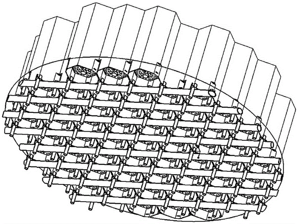
[0045] Such as figure 1 , figure 2 , image 3 , Figure 6 A new type of mist eliminator, including a plurality of demisting units 1 spliced ​​into a honeycomb shape. At the periphery of the flow tube 12 , at least one flow guide tube 12 is arranged in a liquid collecting tube 11 . The primary swirl vane set 13 is installed in the guide tube 12 and is located at the air inlet end thereof. The side wall of the guide tube 12 is provided with a water-permeable structure, and there is a gap between the outer wall surface of the guide tube 12 and the inner wall surface of the liquid collection tube 11 to form a water-passing interlayer cavity 14, and the bottom of the interlayer cavity 14 is connected to the External drain connection.

[0046] The cylinder body of the liquid collecting cylinder 11 is preferably in the shape of a regular hexagon, which facilitates the seamless splicing of adjacent demisting units. A butterfly-shaped bottom plate is provided below the interlaye...

Embodiment 2

[0051] On the basis of Embodiment 1, the honeycomb structure of the liquid collection cylinder 11 can be further simplified, and the liquid collection cylinder 11 is set as Figure 4 , Figure 5 In the structural form shown, a plurality of guide tubes 12 can be arranged in each liquid collecting cylinder 11, and the cylinder wall of the liquid collecting cylinder 11 is composed of several equal-width wall plates connected in sequence, and the included angle between adjacent wall plates is 12°. °, the recess is arranged at the corner of the liquid collection tube 11, so that each guide tube 12 is at least opposite to one wall of the liquid collection tube.

Embodiment 3

[0053] When the mist eliminator is used to separate mist droplets with extremely small particle diameters, such as mist droplets of tens to hundreds of nanometers, several secondary swirl vane groups can be added in the rear section of the primary swirl vane group 13 in the draft guide tube 15. In order to avoid the increased pressure loss of the mist eliminator due to the increase in the number of layers of the blade group, the center piece 151 of the secondary swirl blade group 15 is set as a hollow cylinder, but compared with the blade air inlet of the secondary swirl blade group position, the central piece 151 will be longer on the side facing the air flow. Correspondingly, the interlayer chamber is also separated into separate chamber units, and each chamber unit collects the droplets separated by the corresponding swirl vane groups on each layer, and the drain outlet of the upper chamber unit is connected to the lower chamber unit. Connected, or connected to an external ...


PUM


Abstract

The invention discloses a novel demister comprising more than one demisting unit and is characterized in that each demisting unit comprises flow guiding barrels, rotational flow blade groups arranged at the air inlets of the flow guiding barrels, and liquid collection barrels arranged outside the flow guiding barrels, wherein one liquid collection barrel is internally provided with at least one flow guiding barrel; the side wall of each flow guiding barrel is provided with a water permeable structure; a gap is reserved between the outer wall surface of each flow guiding barrel and the inner wall surface of the corresponding liquid collection barrel to form an interlayer containing cavity. The novel demister disclosed by the invention is arranged in an air treating device and is used for gas-liquid separation, air entering the demister can form a rotation flow state after passing through the rotational flow blade groups; fogdrops carried in the air are thrown to the walls of the flow guiding barrels, enter the interlayer containing cavities of the flow guiding barrels and the liquid collection barrels by the water permeable structures on the walls of the flow guiding barrels, and are discharged from the containing cavities; gas-liquid channels in a demisting process are separated, so that the secondary carrying of the fogdrops in the air can be effectively reduced, and the demisting efficiency is obvious improved.

Description

technical field [0001] The invention relates to a gas-liquid separation device used in the industrial field, in particular to a new type of mist eliminator suitable for industrial applications. Background technique [0002] Gas-liquid separation is a common process in the industrial field. In the wet desulfurization process, the smaller slurry particle size helps the gas-liquid reaction to proceed quickly. However, the flue gas after desulfurization will be saturated with slurry droplets , Small-sized mist droplets are easily carried and discharged by the airflow, causing contamination and serious corrosion of fans, heat exchangers and flue ducts. Therefore, the purified flue gas needs to be defogged before leaving the absorption tower. Most of the existing demisters have a removal efficiency of more than 70% for 20-micron droplets, but only about 30% for 10-micron droplets. The main reason for the excessive particulate matter at the outlet of the desulfurization tower is fo...

Claims


Application Information

Patent Timeline
IPC IPC(8): B01D45/16B01D45/04
CPCB01D45/16B04C3/06B04C2003/006B01D45/12B01D19/0057B01D53/78B01D2258/0283
Inventor 聂江宁凌斌徐家礼
Owner JIANGSU LANSHAN ENVIRONMENT TECH
Features
  • R&D
  • Intellectual Property
  • Life Sciences
  • Materials
  • Tech Scout
  • Unparalleled Data Quality
  • Higher Quality Content
  • 60% Fewer Hallucinations
Learn More