A water cooling device for vacuum evaporation equipment for optical filters

A water-cooling device and optical filter technology, which is applied in vacuum evaporation plating, sputtering plating, ion implantation plating, etc., can solve the problems of device failure, device damage, and increased cost, so as to improve work efficiency, The effect of relieving high temperature and prolonging the use time

Active Publication Date: 2017-10-13
SUZHOU OFT OPTICAL TECH CO LTD
View PDF6 Cites 0 Cited by
  • Summary
  • Abstract
  • Description
  • Claims
  • Application Information

AI Technical Summary

Problems solved by technology

Especially in the industry, the research of water-cooling devices has been paid much attention. In the industry, the devices will generate heat, and when the heat is too large, it is necessary to discharge or cool the heat without affecting these devices. Otherwise, these devices may There will be damage, which will cause the device to fail to work, and also increase the cost. The general device uses a heat release device to discharge the heat generated by the device to achieve continuous and long-term work. However, for the filter vacuum evaporation equipment, The equipment needs to work continuously and uninterruptedly, and the heat generated by the electrode rods in the equipment needs to be discharged urgently, but the general radiator cannot work for a long time, and the exhaust device can only relatively slow down the increase of the heat, so as to Fundamentally, it is impossible to cool down quickly, resulting in low work efficiency.

Method used


Image

  • A water cooling device for vacuum evaporation equipment for optical filters
  • A water cooling device for vacuum evaporation equipment for optical filters
  • A water cooling device for vacuum evaporation equipment for optical filters

Examples


Embodiment 1

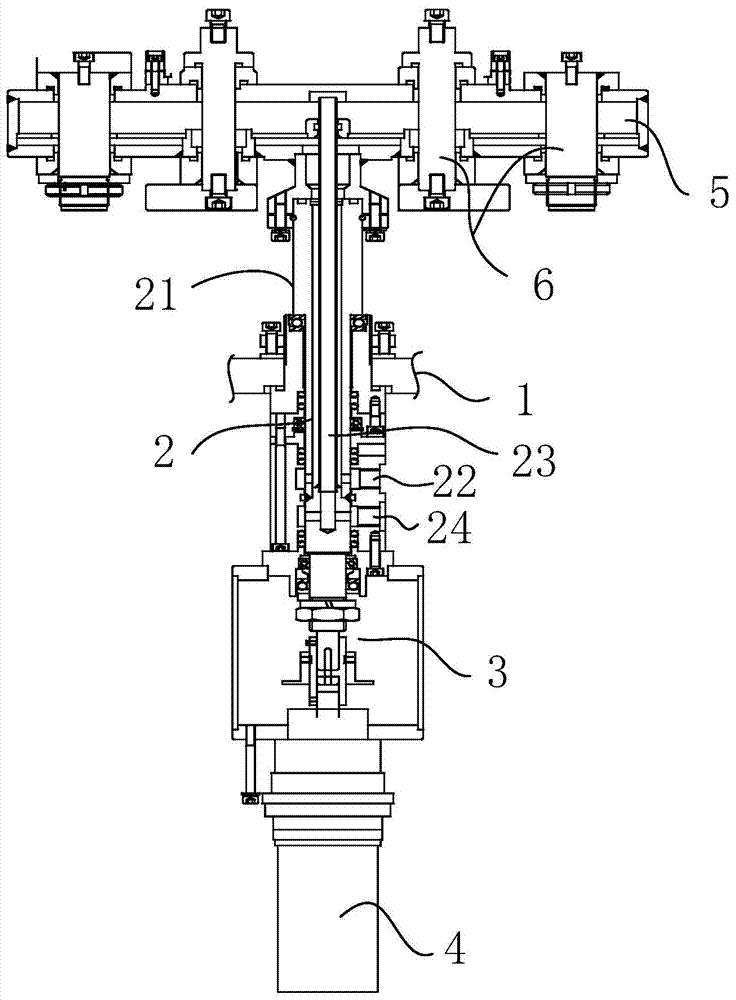
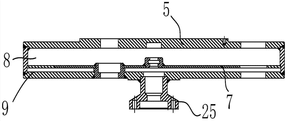
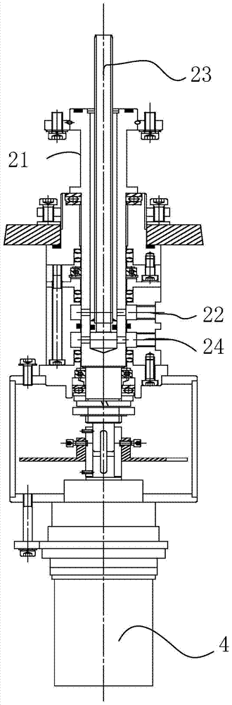
[0037]In Embodiment 1, the present invention provides a water cooling device for vacuum evaporation equipment for optical filters, including: a mounting plate 1, a rotating shaft 2 is connected to the mounting plate 1, and the rotating shaft One end of the shaft 2 is driven and connected to the motor 4 through a coupling 3, and the other end of the rotating shaft 2 is fixed to the bottom end of the water cooling plate 5; the inner cavity of the water cooling plate 5 is divided into an upper chamber layer by a partition 7 8 and the lower cavity layer 9, the partition plate 7 is provided with holes, so that the upper cavity layer 8 and the lower cavity layer 9 are communicated and arranged, and a plurality of electrode rods 6 are plugged on the water cooling plate 5, and the electrode rods 6 The upper and lower ends protrude from the upper and lower ends of the water cooling plate 5; the inner cavity of the rotating shaft 2 is inserted with a water outlet pipe 23, and one end of ...

Embodiment 2

[0039] On the basis of the first embodiment, the present invention proposes the second embodiment. The bottom end of the water-cooling plate 5 in the second embodiment is equipped with a cooling pipe joint 25, and the cooling pipe joint 25 is in a Y-shaped structure. Quick disassembly for operation and easy maintenance.


PUM


Abstract

The invention relates to a water cooling device used for vacuum evaporation equipment for optical filters. A rotating shaft is connected to a mounting and fixing plate. One end of the rotating shaft is driven and connected to a motor, and the other end is fixed to the bottom of a water cooling plate; The inner cavity of the plate is divided into an upper cavity layer and a lower cavity layer by a partition, and the upper cavity layer and the lower cavity layer are arranged in communication; a water outlet pipe is inserted into the inner cavity of the rotating shaft, and one end of the water outlet pipe extends into the water cooling plate. In the upper chamber layer, it is connected with the upper chamber layer, and the other end is connected to the water outlet of the water outlet pipe. The water inlet pipe is set on the rotating shaft. One end of the water inlet pipe is connected with the lower chamber layer of the water cooling plate, and the other end is connected to the water inlet pipe. Shuikou. In the present invention, the water outlet pipe is installed in the rotating shaft, and the water inlet pipe is set outside the rotating shaft. One end of the water outlet pipe is connected with the upper chamber layer, and one end of the water inlet pipe is connected with the lower chamber layer, effectively reducing the length of the electrode rod. The high temperature generated by working for a long time increases its service time, thereby improving work efficiency.

Description

technical field [0001] The invention relates to a water cooling device, in particular to a water cooling device used in vacuum evaporation equipment for optical filters. Background technique [0002] Water cooling devices are widely used in various fields of industry and agriculture, and cooling equipment can be seen everywhere in people's lives, and it is one of the indispensable process equipment. Especially in the industry, the research on water-cooling devices has been paid much attention. In the industry, the devices will generate heat, and when the heat is too large, it is necessary to discharge or cool the heat without affecting these devices. Otherwise, these devices may There will be damage, which will cause the device to fail to work, and also increase the cost. The general device uses a heat release device to discharge the heat generated by the device to achieve continuous and long-term work. However, for the vacuum evaporation equipment for optical filters, The ...

Claims


Application Information

Patent Timeline
Patent Type & Authority Patents(China)
IPC IPC(8): C23C14/24
Inventor 赵培何清
Owner SUZHOU OFT OPTICAL TECH CO LTD
Why Eureka
Try Eureka