Harmonic gear reducer

A gear reducer and harmonic technology, applied in the direction of gear transmission, belt/chain/gear, transmission, etc., can solve the problems of small meshing interval, serious stress concentration at the tooth root, and easy distortion of sharp-point meshing flexible splines , to achieve the effect of expanding the meshing area of ​​the gear teeth, reducing the stress concentration of the tooth root, and facilitating the formation of the oil film

Active Publication Date: 2016-02-03
瑞邦智能科技(南京)有限公司
View PDF8 Cites 20 Cited by
  • Summary
  • Abstract
  • Description
  • Claims
  • Application Information

AI Technical Summary

Problems solved by technology

However, the commonly used involute tooth-shaped harmonic drive has many disadvantages: the stress concentration at the root of the tooth is serious, and it is prone to fatigue fracture; the contact stress of the gear teeth is large, and the meshing interval is small, which affects the bearing capacity; Distortion occurs, it is difficult to achieve high stiffness, and it will cause meshing tooth profile interference or sliding teeth, which seriously restricts the overall load-carrying capacity
Although the ordinary double-arc tooth profile improves the load-carrying capacity to a certain extent, its manufacturing capacity is greatly limited due to the inability to change its position, and it lacks practical use value
The research on the tooth shape, parameters and structural design of harmonic transmission is not deep enough, and it is far behind the performance requirements of harmonic transmission devices for specific working conditions such as robot joints and aerospace servo mechanisms, which restricts the development of robotics and other precision transmission technologies

Method used


Image

  • Harmonic gear reducer
  • Harmonic gear reducer
  • Harmonic gear reducer

Examples


Embodiment 1

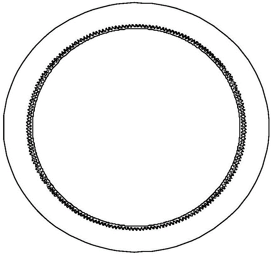
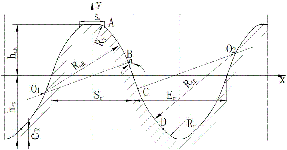
[0028] combine image 3 , image 3 is the tooth profile curve of the flexspline 1 of the harmonic gear reducer of the present invention. The flexible gear 1 of the harmonic gear reducer of the present invention is processed by displacement cutting of a hobbing cutter. The basic tooth profile curve of the flexspline 1 is composed of arc-involute-arc. In this embodiment, the basic tooth profile parameters of the flexspline 1 are:

[0029] Addendum height factor root height factor Headspace Coefficient Pressure angle α=20°, coefficient of variation x R =3.52, the arc radius coefficient of the tooth top working section Radius coefficient of the arc radius of the working section of the dedendum Tooth thickness ratio K=1.05, root transition arc radius coefficient Addendum thickness factor In order to prevent the tooth tip interference phenomenon of the tooth profile of the flexspline during the meshing process, the tooth tip part is rounded, and the fillet radius coe...


PUM


Abstract

The invention discloses a harmonic gear reducer which comprises a flexible gear, a rigid gear and an elliptical cam wave generator. The cup bottom of the flexible gear is connected with an output shaft. The elliptical cam wave generator is connected with an input shaft. The outer wall, along the cup rim, of the flexible gear is provided with an arc-involute-arc-tooth profile. The elliptical cam wave generator is arranged on the inner wall of the cup rim of the flexible gear. The rigid gear is fixedly connected with a shell and the inner wall is provided with an arc-involute-arc-tooth profile matched with the flexible gear tooth profile. The rigid gear is connected with the flexible gear through the tooth profiles in an engaged manner. In the engagement process, the flexible gear is in continuous conjugated engagement with the rigid gear, a convex tooth profile and a concave tooth profile of the flexible gear and a concave tooth profile and a convex tooth profile of the rigid gear are located in the double-conjugation engagement interval of the conjugation motion at the same time. The harmonic gear reducer has the beneficial effects that both arc tooth-shaped harmonic driving and involute-tooth-shaped harmonic driving are achieved; and deflection driving can be achieved, the gear tooth engagement region can be enlarged, and the engagement rigidity, driving efficiency and bearing capacity of the harmonic gear reducer are improved.

Description

technical field [0001] The invention relates to the technical field of harmonic transmission, in particular to a harmonic gear reducer. Background technique [0002] Harmonic transmission has many unique advantages such as simple structure, light weight, large transmission ratio range, high transmission precision, small backlash, large number of meshing teeth at the same time, and the ability to transmit motion and power to confined spaces. In recent decades, harmonic gear transmission technology and transmission devices have been widely used in space technology, machine tools, instruments, robots, automobiles, shipbuilding, textiles, metallurgy, conventional weapons, precision optical equipment, printing and packaging machinery, and medical equipment, etc. field. The application practice at home and abroad has proved that whether it is a precision harmonic drive as a high-sensitivity servo system or a power harmonic drive that transmits high torque, it has shown good perfo...

Claims


Application Information

Patent Timeline
Patent Type & Authority Applications(China)
IPC IPC(8): F16H1/34
Inventor 范元勋王敏杰王华坤宋德峰祖莉
Owner 瑞邦智能科技(南京)有限公司
Why Eureka
Try Eureka