Two-drum spraying denitration settling separation corner-tube boiler

A technology of settling separation and corner tube boilers, which is applied in the field of boilers

Active Publication Date: 2016-02-10
孙宇健
View PDF7 Cites 1 Cited by
  • Summary
  • Abstract
  • Description
  • Claims
  • Application Information

AI Technical Summary

Problems solved by technology

[0002] As we all know, the current structure of corner tube boilers is that four unheated downtubes are arranged around the boiler body as supports. The boiler has low strength and weak supports, which may easily cause safety accidents.
Since the overall layout of corner tube boilers is limited by strength, it is not conducive to the manufacture of large boilers
The grate length of ordinary corner tube boilers cannot be fully extended, the fuel combustion is insufficient, the coal combustion efficiency is low, and inferior coal cannot be burned, the carbon content is high, and the energy consumption is large
The flue gas at the outlet of the furnace directly washes the serpentine tube of the flag-type heating surface, which is severely worn. There is no settling chamber, the dust cannot settle, the heating surface is small, the service life is low, the maintenance rate is high, and the use cost is increased.
With the increasingly stringent national environmental protection policies, the known corner tube boilers cannot meet the national emission requirements for boiler air pollutant emission standards, and the concentration of nitrogen oxide emissions is high, polluting the environment

Method used


Image

  • Two-drum spraying denitration settling separation corner-tube boiler
  • Two-drum spraying denitration settling separation corner-tube boiler
  • Two-drum spraying denitration settling separation corner-tube boiler

Examples


Embodiment Construction

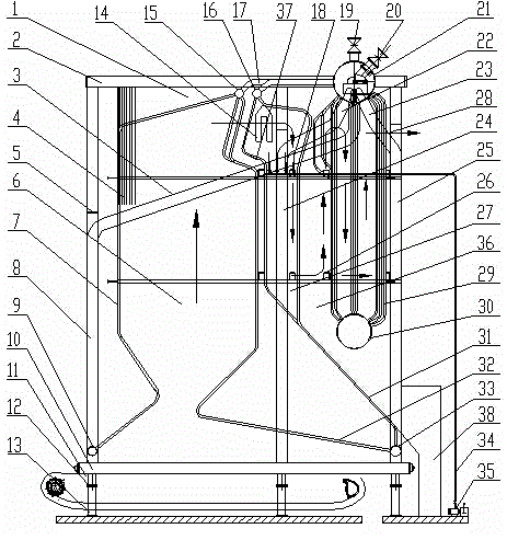
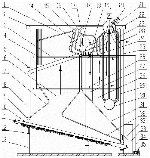
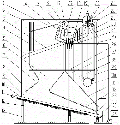
[0022] Specific embodiments of the present invention, such as Figure 1-4 As shown, a double-drum spray denitrification settlement separation angle tube boiler includes a boiler body part and a grate part. The boiler body part includes a boiler body 1, and four supporting boilers are vertically arranged around the boiler body 1. The left side supports the downcomer 8 and the right side of the boiler supports the rear arch feedwater downcomer 25, the upper drum 21 and the lower drum 30 arranged on the upper right part of the boiler body 1, and the convection tube bundle 29 between the upper drum 21 and the lower drum 30 , the water inlet pipe 20 and the water outlet pipe 19 connected with the upper drum 21, the front arch descending pipe 3 and the rear arch descending pipe 23, and the upper return pipe 17, the superheater 14, the side wall water cooling wall 4, the furnace 6, and the front arch water cooling wall 7. Front arch lower header 9, side wall water wall upper header 2...


PUM


Abstract

The invention relates to a two-drum spraying denitration settling separation corner-tube boiler, comprising a boiler body part and a fire grate part, wherein the fire grate part is arranged at the bottom of the boiler body part; the boiler is characterized in that a boiler body 1 is provided with a boil supporting mechanism, a boiler water circulation mechanism and a spraying denitration cyclone separation settling device, the boil supporting mechanism is formed by two vertically arranged side cooling wall supporting downcomers 24, a side wall water supply downcomer 22 communicated with the side cooling wall supporting downcomers 24, and supporting stiffening beams 26 arranged vertically and horizontally, the boiler water circulation mechanism is formed by a channel rear wall water cooling wall 31, a second channel rear wall water cooling wall 37, and an upper header 16 and a lower header 33 of a settling box, and the spraying denitration cyclone separation settling device is formed by denitration spraying pipes 34, denitration nozzles 18, a denitration agent supplier 35, an upper settling separation chamber 27 and a lower settling separation chamber 28. The two-drum spraying denitration settling separation corner-tube boiler has the characteristics of being high in supporting strength, stable in structure, capable of reducing nitric oxide emission, reducing air pollution and improving thermal efficiency, energy-saving, environment-friendly, safe and the like.

Description

technical field [0001] The invention relates to the technical field of boilers, in particular to a double-drum spraying, denitrification, sedimentation and separation angle tube boiler that can meet the discharge requirements of the national boiler air pollutant discharge standard and solve the problem of high nitrogen oxide discharge concentration and environmental pollution. Background technique [0002] As we all know, the current corner tube boiler structure is that four unheated downcomers are arranged around the boiler body as supports, the boiler strength is low, and the support is not firm, which is easy to cause safety accidents. Because the overall layout of corner tube boilers is limited by strength, it is not conducive to the manufacture of large boilers. The grate length of ordinary corner tube boilers cannot be fully extended, the fuel combustion is insufficient, the coal combustion efficiency is low, and inferior coal cannot be burned, the carbon content is ...

Claims


Application Information

Patent Timeline
Patent Type & Authority Applications(China)
IPC IPC(8): F22B31/08F24H1/24F23B30/08F23J15/04B01D53/78B01D53/56
Inventor 孙宇健
Owner 孙宇健
Why Eureka
Try Eureka