
All-fiber quarter wave plate packaging method

A packaging method and all-fiber technology, applied in the direction of voltage/current isolation, etc., to achieve good sealing, simple structure, and long-term use stability

Active Publication Date: 2016-02-10
BEIJING AUTOMATION CONTROL EQUIP INST
View PDF13 Cites 1 Cited by
  • Summary
  • Abstract
  • Description
  • Claims
  • Application Information

AI Technical Summary

Problems solved by technology

[0005] At present, there is no recognized and effective packaging method for all-fiber quarter-wave plates in the industry. How to package all-fiber quarter-wave plates to ensure that the volume of the wave plate is suitable and the performance is stable and reliable is an urgent problem to be solved when using optical fiber current transformers. one of the key issues of

Method used


Image

  • All-fiber quarter wave plate packaging method
  • All-fiber quarter wave plate packaging method

Examples


Embodiment Construction

[0031] The technical solution of the present invention will be further described in detail below in conjunction with the accompanying drawings.

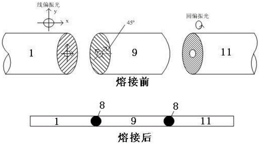
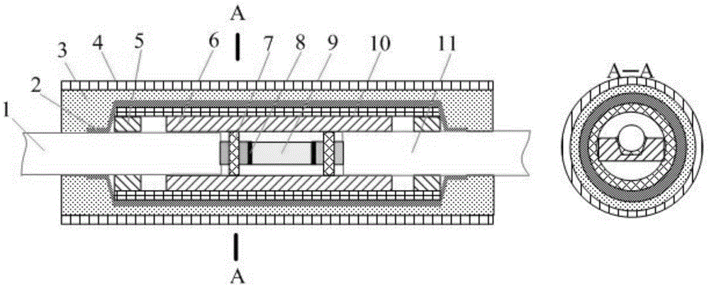
[0032] like figure 2 Shown is a schematic diagram of the packaging structure of the fiber end reflector of the present invention. The packaging process of the all-fiber quarter-wave plate of the present invention mainly includes the following steps:

[0033] (1) Place the all-fiber quarter-wave plate horizontally in the middle of the slotted quartz plate, and reserve the same distance between the left and right ends of the quartz plate;

[0034] In this embodiment, the shape of the groove on the quartz plate is one of the following two shapes: trapezoidal or U-shaped.

[0035] (2) At a distance of 1 to 1.5 mm from the left and right ends of the full-fiber quarter-wave plate, apply the first fiber-optic fixing glue, heat and cure, and then let it stand; glue can be dispensed multiple times, and the gap can be filled with heating. ...


PUM


Abstract

The invention belongs to the technical field of a fiber current transformer and specifically relates to an all-fiber quarter wave plate packaging method. The method provides a manufacturing process flow to meet use requirement of the fiber current transformer through a reasonable three-layer packaging process and based on the practical application situation of the fiber current transformer. The all-fiber quarter wave plate packaging method has the obvious advantages of simple structure, small size, good seal performance, high reliability and stable long-term use, so that an all-fiber quarter wave plate can fully replace a crystal quarter wave plate in the application of the fiber current transformer, and becomes a high-precision, high-stability and high-reliability fiber current transformer core part.

Description

technical field [0001] The invention belongs to the technical field of optical fiber current transformers, and in particular relates to a packaging method for an all-fiber quarter-wave plate. Background technique [0002] Optical fiber current transformer is an ideal product to replace traditional current transformers. It has the characteristics of good insulation, no magnetic saturation and high safety. It is the first choice in the development plan of my country's smart grid. status and broad market prospects. The main working principle of fiber optic current transformer is to use the Faraday effect of magneto-optical materials. Using the magnetic field generated by the alternating current to act on the two beams of circularly polarized light with opposite transmission directions in the optical fiber, the direction of the electric field is rotated, which is equivalent to the phase shift in time, and the current to be measured is detected through the phase shift. [0003] ...

Claims


Application Information

Patent Timeline
Patent Type & Authority Applications(China)
IPC IPC(8): G01R15/24
Inventor 杨怿吴衍记许刚向强章敏段俊杰
Owner BEIJING AUTOMATION CONTROL EQUIP INST
Learn More