Combined type multi-layer composite electrical connection structure for inversion device

A technology of electrical connection and converter device, applied in the direction of connection, fixed connection, electrical components, etc., can solve the problems of low reliability, large space, high cost, improve system reliability, reduce peak voltage, and reduce overall cost Effect

Active Publication Date: 2016-02-10
ZHUZHOU CSR TIMES ELECTRIC CO LTD
View PDF5 Cites 2 Cited by
  • Summary
  • Abstract
  • Description
  • Claims
  • Application Information

AI Technical Summary

Problems solved by technology

[0003] 1. The electrical clearance requirement is high and the space occupied is too large;
[0004] 2. The layout of cables takes up too much wiring space, and the wiring construction is difficult;
[0005] 3. Moreover, due to the large number of connection points and the staggered complex points, the cable layout will inevitably be staggered and complicated, the wiring is easy to cause errors, and the heat generated by the densely populated parts is high
[0006] 4. The cable is long, the inductance is large, and the cost is high;
[0007] 5. Low anti-interference ability and low reliability

Method used


Image

  • Combined type multi-layer composite electrical connection structure for inversion device
  • Combined type multi-layer composite electrical connection structure for inversion device
  • Combined type multi-layer composite electrical connection structure for inversion device

Examples


Embodiment Construction

[0026] The present invention will be further described in detail below in conjunction with the accompanying drawings and specific embodiments.

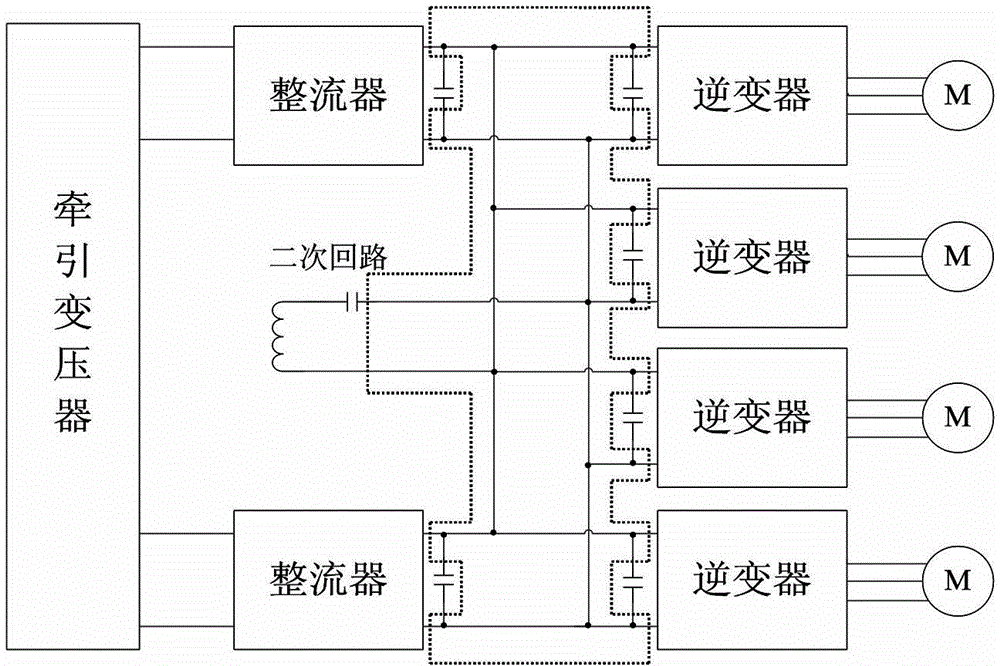
[0027] Such as figure 1 As shown, it is a specific application example of the converter device, in which the converter device adopts a symmetrical layout structure in design, with a rectifier and two inverters as a group, and each group is connected to the secondary circuit (by the inductor and a resonant circuit composed of capacitors). The circuit between the rectifier and the inverter is often designed as an intermediate DC circuit, and there is a complex circuit connection between the intermediate DC circuit and the secondary circuit, with many connection points and complex types, as shown in the circuit part in the dotted line box in the figure, namely For the application object of the present invention. In this dotted line box, the circuit as a whole presents a symmetrical structure.

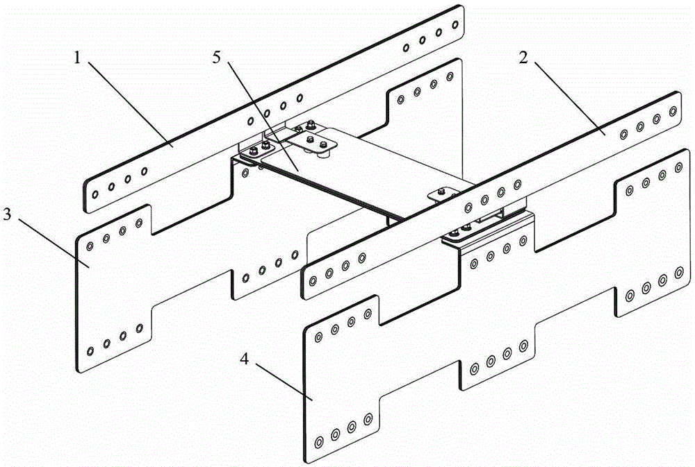
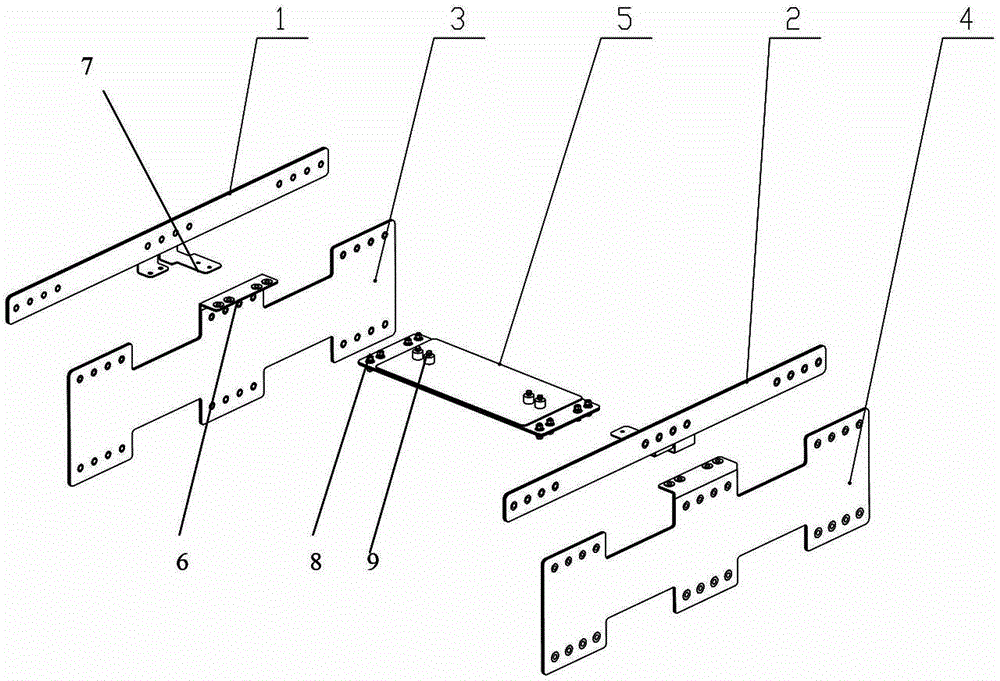
[0028] Such as figure 2 with image 3...


PUM


Abstract

The present invention provides a combined type multi-layer composite electrical connection structure for an inversion device. The structure of a first secondary circuit busbar of the combined type multi-layer composite electrical connection structure is identical to the structure of a second secondary circuit busbar of the combined type multi-layer composite electrical connection structure, and the first secondary circuit busbar and the second secondary circuit busbar are electrically connected with a secondary circuit of the inversion device. The structure of a first middle DC circuit busbar of the combined type multi-layer composite electrical connection structure is identical to the structure of a second middle DC circuit busbar of the combined type multi-layer composite electrical connection structure, and the first middle DC circuit busbar and the second middle DC circuit busbar are connected with DC circuits of a rectifier and an inverter. The first secondary circuit busbar and the first middle DC circuit busbar form a group, the second secondary circuit busbar and the second middle DC circuit busbar form another group, and the two groups are arranged on two ends of a busbar symmetrically. The bus bar is used for the circuit connection of secondary circuits of the first secondary circuit busbar and the second secondary circuit busbar, the DC circuit connection of DC circuits of the first middle DC circuit busbar and the second middle DC circuit busbar, and the circuit connection of the DC circuit and the secondary circuit. The combined type multi-layer composite electrical connection structure for the inversion device has simple and compact structure, is low in cost, is convenient to install, has better heat dispersion performance and the like.

Description

technical field [0001] The invention mainly relates to the field of electrical connection structures, in particular to a combined multilayer composite electrical connection structure suitable for converter devices. Background technique [0002] Composite busbar is an electrical connection form often used in electrical systems. It has the advantages of large carrying capacity, low inductance, small heat generation, compact structure, and convenient installation. For example, there is an intermediate DC circuit composite busbar in the converter device. Row. The electrical connection of electrical system equipment has the characteristics of a large number and types of contacts. The conventional technical solution uses a cable connection scheme. The cable surface insulation layer is relatively thick, and the bending radius is large, and there are many wire harnesses. This cable connection method mainly has the following disadvantages: [0003] 1. The electrical clearance requi...

Claims


Application Information

Patent Timeline
Patent Type & Authority Applications(China)
IPC IPC(8): H01R12/61H02M1/00H02M5/42
Inventor 刘大程俊周汉刘永江陈斌
Owner ZHUZHOU CSR TIMES ELECTRIC CO LTD
Why Eureka
Try Eureka