Lap winder for winding strips of cotton wool to lap rolls

A technology for winding machines and sliver rolls, applied in winding mechanisms, winding strips, textiles and papermaking, etc., can solve problems such as negative productivity, and achieve the effects of optimizing productivity, optimizing adjustment, and optimizing winding quality

Active Publication Date: 2016-02-10
TRUETZSCHLER GRP SE
View PDF10 Cites 5 Cited by
  • Summary
  • Abstract
  • Description
  • Claims
  • Application Information

AI Technical Summary

Problems solved by technology

Air bubble formation can be avoided by lower winding

Method used


Image

  • Lap winder for winding strips of cotton wool to lap rolls
  • Lap winder for winding strips of cotton wool to lap rolls
  • Lap winder for winding strips of cotton wool to lap rolls

Examples


Embodiment Construction

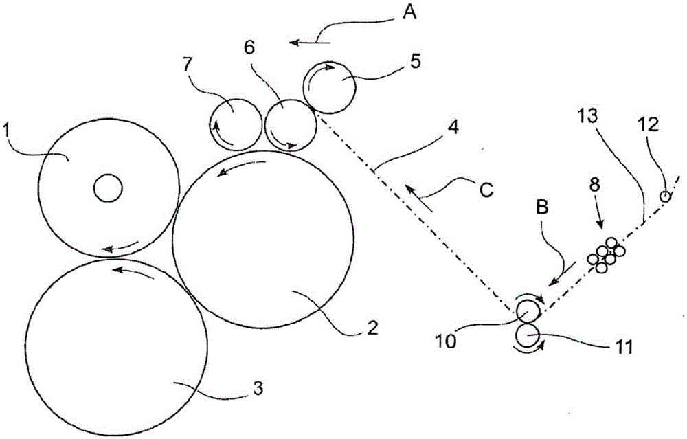
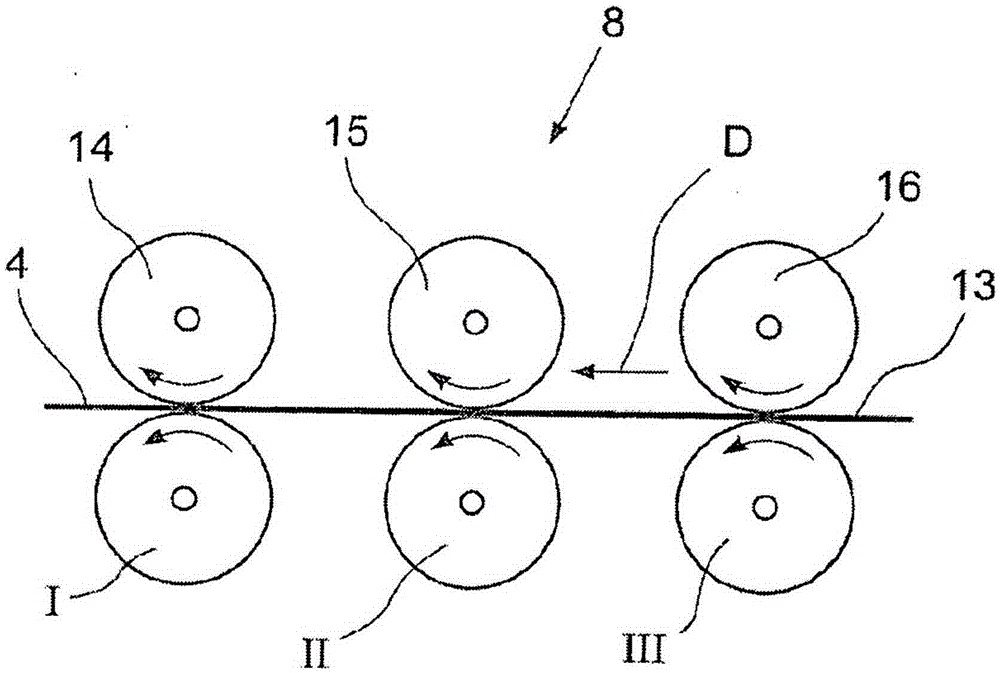
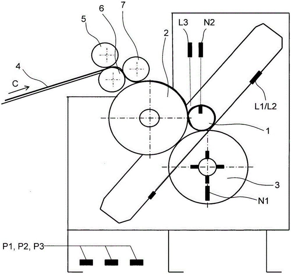
[0023] according to figure 1 , Cotton lap 1 is laid on the two winding rolls 2 and 3 (winding calender) of the belt winding machine which can rotate in the direction of the arrow. The sliver 4 (shown in dashed lines) passes through a calender (pressure calender) consisting of three press rollers 5 , 6 and 7 , then leads to the lap 1 and is wound up on the lap. The sliver 4 is formed in the drafting device 8 of the tape winder from one or more supplied nonwovens or from drafting strips 13 next to each other. One drafting device 8 ′ or several drafting devices can also be connected upstream to the drafting device 8 . A table calender consisting of two rolls 10 , 11 is arranged between the delivery roll 14 / I of the drafting device 8 and the press roll 5 of the pressure calender. The deflection roll 12 is arranged upstream of the feed roll 16 / III of the drafting device 8 , and the fiber sliver 13 from the upstream (not shown) fiber can and (not shown) creel (gatter) is deflec...


PUM


Abstract

The invention relates to a lap winder for winding strips of cotton wool to lap rolls, said lap winder comprising lap rollers (2, 3) for carrying one lap roll (1) each, pressure rollers (5, 6, 7) for calendering a strip of cotton wool (4) supplied thereto, which pressure rollers are mounted upstream of the lap rollers (2, 3), and at least one drawing system (8) having drawing roller pairs which system is mounted upstream of the pressure rollers (5, 6, 7). The invention is characterized in that each lap roller (2, 3) has a separate drive, and at least one drive can be controlled or regulated by a control unit.

Description

technical field [0001] The invention relates to a winding machine for winding cotton sliver into laps, said winding machine having winding rollers for supporting each lap, said winding machine also having a A pressure roller connected upstream of the winding roller for the sliver, wherein at least one drafting device with a pair of draft rollers is located upstream of the pressure roller. Background technique [0002] The currently usual supply of flat combers takes place via laps which were previously produced from the individual sliver in the winder. Furthermore, the winder contains at least one strip-shaped sample, wherein the sample is temporarily stored in a circular or rectangular cylinder. Winding machines generally comprise a winding unit with at least two winding rollers on which the lap is formed by means of a sleeve. At least one pair of press rollers, which apply and / or draw the strip, are usually upstream of the take-up unit. The entry area is arranged before...

Claims


Application Information

Patent Timeline
IPC IPC(8): D01G27/00B65H18/20
CPCD01G27/00G01N33/36B65H18/20B65H18/26B65H2220/03B65H2408/232B65H2511/11B65H2553/24B65H2701/177B65H2511/14B65H2513/10
Inventor 托马斯·施密茨
Owner TRUETZSCHLER GRP SE
Why Eureka
Try Eureka