A kind of welding rod automatic welding system and automatic welding method

An automatic welding and welding rod technology, applied in welding equipment, arc welding equipment, manufacturing tools, etc., to achieve stable operation, simple equipment, and meet the requirements of welding rod process experiments

Active Publication Date: 2017-03-08
威海大威海洋机器人有限公司
View PDF3 Cites 0 Cited by
  • Summary
  • Abstract
  • Description
  • Claims
  • Application Information

AI Technical Summary

Problems solved by technology

The invention patent (CN 03146445.9) of Illinois Apparatus Engineering Company "Method and Equipment for Pulling Back and Feeding Welding Rod" is actually a kind of welding wire feeding control method introduced, rather than welding rod in the traditional sense; Ni Xuefeng's invention patent (CN 93112593.6) "Continuous electrode" introduces a continuous electrode conveying device for the purpose of providing work efficiency. The wire feeding speed during welding is not affected by the arc voltage and the speed is constant; the patent of Kunshan Huaheng Engineering Technology Center Co., Ltd. ( CN 200710019267.5) "Automatic arc length control device" introduces an automatic arc length control device for argon arc welding. The moving speed of the electrode is affected by the voltage, but because the electrode is a non-melting electrode, it is essentially different from the melting electrode arc welding

Method used


Image

  • A kind of welding rod automatic welding system and automatic welding method
  • A kind of welding rod automatic welding system and automatic welding method
  • A kind of welding rod automatic welding system and automatic welding method

Examples


Embodiment Construction

[0033] The present invention will be described in further detail below in conjunction with the accompanying drawings.

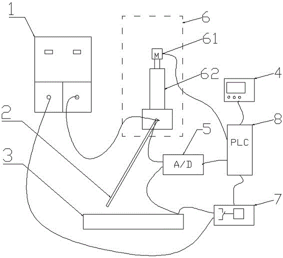
[0034] Such as figure 1 As shown, an automatic electrode welding system includes a welding power source 1, an electrode 2, a workpiece 3, and a human-computer interface 4 for setting parameters, displaying data, and setting the initial feeding speed V 1 , average arc voltage U s , welding rod 2 inclination angle α and welding rod 2 effective burning length L; display real-time feeding speed V, real-time arc voltage U, arc burning state and average voltage and other information, and control the start and stop of the welding process; arc information acquisition system 5, with To collect the welding voltage and welding current data between the electrode 2 and the workpiece 3 in real time, and convert the actual welding current and welding voltage into a 0-10V signal according to the corresponding ratio for control; the motion actuator 6, According to the infor...


PUM


Abstract

The invention discloses an automatic welding system for a welding rod and an automatic welding method. The automatic welding system comprises a welding power source, the welding rod and a work piece, and also comprises a human-computer interaction interface, an electric arc information acquisition system, a motion executing mechanism and a welding power source control module, wherein the human-computer interaction interface is used for setting parameters and displaying data; the electric arc information acquisition system is used for acquiring the data of welding voltage and welding current between the welding rod and the work piece in real time; the motion executing mechanism is used for driving the welding rod to move according to the information acquired by the electric arc information acquisition system and regulating the speed in real time according to a specific control strategy so as to regulate the voltage of the electric arc; the welding power source control module is used for connecting or disconnecting the welding power source according to the information acquired in real time by the electric arc information acquisition system. The automatic welding system disclosed by the invention is simple to clamp; periodic regulation is not needed; the processing is reasonable; the voltage fluctuation range of the electric arc is small during welding; automatic arc striking can be realized; the inclination angle of the welding rod can be regulated; the conveying speed of the welding rod can be automatically regulated; power is automatically cut off after welding is ended.

Description

technical field [0001] The invention relates to the field of welding technology, in particular to an automatic welding system and an automatic welding method for electrodes. Background technique [0002] Electrode arc welding is a traditional welding method in which the welder holds the welding tongs and clamps the electrode for welding. The method has the advantages of simple equipment, flexible operation and wide application. However, because the welding quality of this method is greatly affected by the welder's operation level, the weld quality stability is poor when ordinary welders operate. [0003] In the development process of welding materials and welding equipment, it is often necessary to test the developed products. This type of testing needs to strictly ensure the stability of various relevant factors during the testing process, including welder's techniques. The welder's technique mainly involves the inclination angle of the welding rod, the welding walking sp...

Claims


Application Information

Patent Timeline
Patent Type & Authority Patents(China)
IPC IPC(8): B23K9/095B23K9/235
CPCB23K9/0956B23K9/235
Inventor 郭宁杜永鹏冯吉才
Owner 威海大威海洋机器人有限公司
Why Eureka
Try Eureka