Tool for welding impeller of centrifugal blower

A centrifugal blower, welding tooling technology, applied in welding equipment, auxiliary welding equipment, welding/cutting auxiliary equipment, etc., can solve the problems of increased labor intensity, increased workload, low production efficiency, and difficult to fix, and improve welding processing efficiency. , The effect of reducing the time of grinding welds and saving labor costs

Inactive Publication Date: 2016-02-24
安徽虎渡科达流体机械有限公司
View PDF8 Cites 14 Cited by
  • Summary
  • Abstract
  • Description
  • Claims
  • Application Information

AI Technical Summary

Problems solved by technology

At present, due to the large size and heavy weight of the impeller, the welding equipment used for centrifugal blower impellers is mostly hoisted to the welding station by trusses, and then the welders directly weld or fix the impeller manually. This method is convenient for the impeller to move but not easy to fix. Even if the best welding position is found, it is not easy to weld accurately, which affects the welding quality of the impeller, and at the same time, the production efficiency is low
The patentee is "Shangyu Special Fan Co., Ltd.", and the utility model patent with application number "CN201320643979.5" discloses a welding tool for the centrifugal fan impeller. Although the welding tool has been improved to a certain extent, the welding tool moves , It is inconvenient to turn over, and it cannot fundamentally solve the problem of finding the best welding position and fixing it. At the same time, the use of this tool also requires that the position of the impeller be placed accurately. This method does not reduce the labor intensity but increases the workload, which is not conducive to large-scale industrialization. Production

Method used


Image

  • Tool for welding impeller of centrifugal blower
  • Tool for welding impeller of centrifugal blower
  • Tool for welding impeller of centrifugal blower

Examples


Embodiment Construction

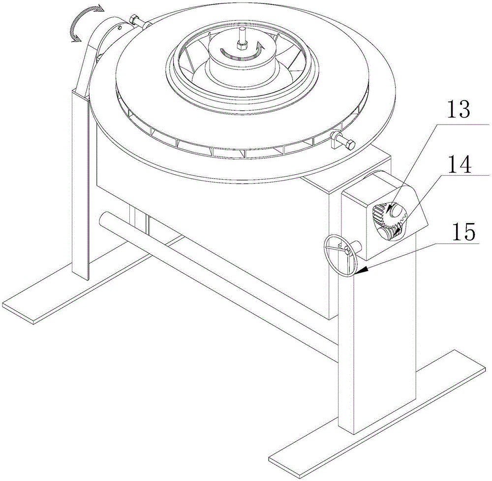
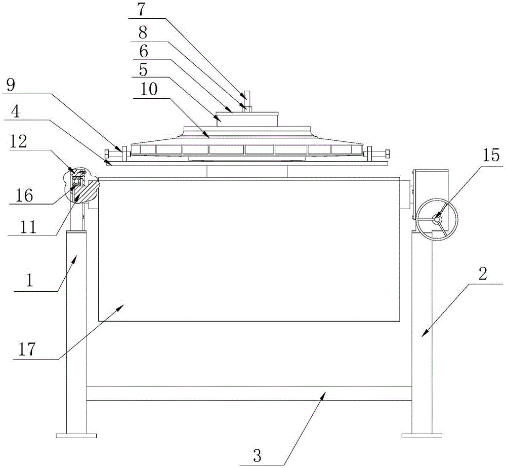
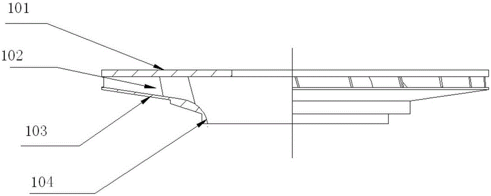
[0011] Referring to the accompanying drawings, the impeller is mainly welded by a wheel disc 101, a wheel cover 103, long and short blades 102, and an inlet ring 104. An impeller welding tool for a centrifugal blower, which includes a bracket, a rotating mechanism and a turning mechanism. The bracket includes a left bracket 1 and a right bracket 2. The left bracket and the right bracket are respectively fixed on the base surface. The space is connected by a reinforcing tube 3; the rotating mechanism includes a support plate 4, a pressure ring 5, a gland 6, a screw rod 7, a nut 8 and a limit fixing bolt 9, and two limit fixing bolts are provided, and the two limit fixing bolts are used to support The center of the disc circle is set symmetrically, and the impeller 10 is connected with the support disc through a pressure ring, gland, screw and nut. The impeller can rotate around the screw rod on the support disc and can be fixed by limit fixing bolts; the turning mechanism includ...


PUM


Abstract

The invention discloses a tool for welding an impeller of a centrifugal blower. The tool comprises a rack, a rotation mechanism and an overturning mechanism. By adopting the tool for welding the impeller of the centrifugal blower disclosed by the invention, the welding quality of the impeller can meet the welding technology requirement; the welding processing efficiency of the impeller is improved; the time which a worker spends on polishing a welding joint is reduced; the labor cost for manufacturing the impeller is reduced; and industrial large-scale production of the tool is facilitated.

Description

technical field [0001] The invention belongs to the field of blower auxiliary equipment, in particular to an impeller welding tool for a centrifugal blower. Background technique [0002] For centrifugal blowers, the impeller, also known as the working wheel, is the most important part of the compressor. The impeller rotates at a high speed with the main shaft to do work on the gas. Under the action of the impeller blades, the gas rotates at a high speed with the impeller, and is affected by the rotating centrifugal force and the diffusion flow in the impeller. When it flows out of the impeller, the pressure, speed and temperature of the gas are all increased. The impeller is mainly welded by the wheel disc, the wheel cover, the long and short blades, and the inlet ring. According to the design requirements of the fan, a certain number of long and short blades are evenly welded between the wheel disc and the wheel cover, and the space for welding operation is narrow, so the...

Claims


Application Information

Patent Timeline
Patent Type & Authority Applications(China)
IPC IPC(8): B23K37/04B23K37/047B23K37/00
CPCB23K37/0443B23K37/006B23K37/047B23K2101/001
Inventor 胡兵廖福建苏春模李万享王小银
Owner 安徽虎渡科达流体机械有限公司
Why Eureka
Try Eureka