Pipeline leakage recognizing and positioning system and method based on sound wave imaging

A technology of pipeline leakage and positioning system, which is applied in the field of leakage identification of fluid conveying pipelines, and can solve the problems of large propagation attenuation, inability to use old pipelines for monitoring, submersion, etc.

Active Publication Date: 2016-02-24
NANJING QIAOSHENG FLUCTUATION TECH
View PDF5 Cites 26 Cited by
  • Summary
  • Abstract
  • Description
  • Claims
  • Application Information

AI Technical Summary

Problems solved by technology

There are five disadvantages of the negative pressure wave method (sonic method): one is that it is easily affected by the impact interference sound (such as excavation sound, car rolling sound, knocking sound) in the environment where the pipeline is located, resulting in false alarms; Man-made theft leakage, in the artificially controlled slow-release process, the amplitude of the negative pressure wave is small, it is easy to be overwhelmed by the background noise and the system cannot detect it, resulting in false alarms, and it is also easy for some pores below 3mm to leak Due to the weak negative pressure wave pulse generated, it is missed; third, it can only detect sudden pressure changes, and cannot monitor the continuous leakage process, resulting in poor ability to eliminate interference; The propagation and attenuation of negative pressure waves caused by spontaneous leakage in pipelines are quite different, and the propagation attenuation in liquid media such as water and oil is small, while the propagation attenuation in gaseous media such as natural gas and coal gas is large. The upper application effect is poor; the fifth is that the ambient temperature and the temperature change in the pipeline cause the change of the sound velocity in the medium, and the sound velocity in different media is very different, and the positioning error caused by the inconsistency of the upstream and downstream sound velocities of the leak point cannot be eliminated, resulting in The location error of the leak point is large
The disadvantage of the optical fiber method is that the laying cost is high, and it cannot be used for the monitoring of old pipelines. At the same time, it is easily disturbed by the vibration and shock around the pipeline, resulting in false alarms.

Method used


Image

  • Pipeline leakage recognizing and positioning system and method based on sound wave imaging
  • Pipeline leakage recognizing and positioning system and method based on sound wave imaging
  • Pipeline leakage recognizing and positioning system and method based on sound wave imaging

Examples


Embodiment 1

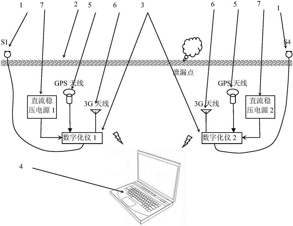
[0044] This embodiment provides a pipeline leakage identification and location monitoring system based on acoustic wave imaging including two pipeline infrasonic sensors, such as figure 1 shown.

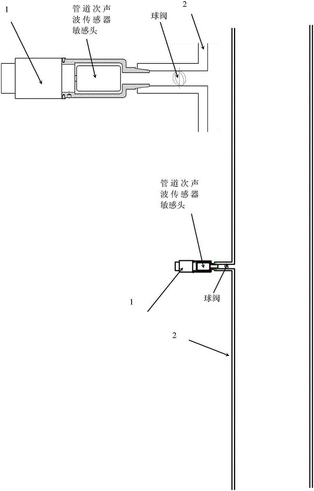
[0045] Under normal circumstances, the pressure in the pipeline is not lower than 0.01MPa, and the leakage hole diameter is greater than 1mm. The diameter of the pipeline is less than 2m, and the length of the pipeline is less than 100km. A high-consistency pipeline infrasonic wave sensor 1 is respectively installed at both ends of the tested pipeline 2. The pipeline infrasonic wave sensor is installed on the wall of the tested pipeline, and the sensitive head of the pipeline infrasonic wave sensor passes through the opening on the measured pipeline wall and the medium in the pipe Connected, the sensitive head is completely immersed in the medium in the pipeline under test. There are two ways to install the pipeline infrasonic sensor and the pipeline under test, one way is as fig...

Embodiment 2

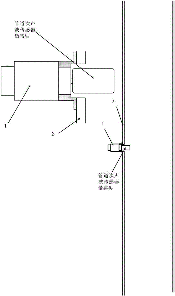
[0054] This embodiment provides a monitoring system for identifying and locating pipeline leaks based on acoustic wave imaging including four pipeline infrasonic sensors, such as image 3 shown.

[0055] Embodiment 2 differs from Embodiment 1 only in that two high-consistency pipeline infrasonic sensors are installed at both ends of the pipeline, and the distance between the two pipeline infrasonic sensors at each end is a definite value that can be accurately measured, and The two pipeline infrasonic sensors are connected to the same digitizer, and converted into digital signals according to the same time base sampling, which ensures that the time synchronization error of the two signals is negligibly small. According to the signal received by two pipeline infrasonic wave sensors at the same end from the same leaking sound source, the true velocity of sound waves propagating in the pipeline can be calculated. The dual sensor signals at the upstream end allow the calculation ...


PUM


Abstract

The invention relates to a pipeline leakage recognizing and positioning system and method based on sound wave imaging. The pipeline leakage recognizing and positioning system and method are mainly characterized in that the system comprises pipeline infrasonic wave sensors, digitalizers, direct-current voltage stabilizing power sources and a monitoring server; the pipeline infrasonic wave sensors are arranged at the two ends of a measured pipeline respectively, and sensing heads of the pipeline infrasonic wave sensors are in complete contact with a medium in the pipeline and immersed in the medium in the pipeline through open holes in the measured pipeline; the pipeline infrasonic wave sensors upload measured signals to the monitoring server through the digitalizers; and the monitoring server calculates a sound and image graph for sound pressure distribution in the part, between the two pipeline infrasonic wave sensors, of the pipeline according to the measured signals uploaded by the two digitalizers, and the position and strength of a leakage sound source are recognized on the sound and image graph. According to the pipeline leakage recognizing and positioning system and method based on sound wave imaging, leakage is recognized based on the stability of the sound and image graph according to the wideband characteristic of leaking sounds, the accuracy of leakage recognition is improved and reaches more than 95%, the rate of false alarms is lower than 5%, the leakage process can be reflected, and the leakage flow is estimated.

Description

technical field [0001] The invention belongs to the technical field of leakage identification of fluid conveying pipelines, in particular to a pipeline leakage identification and positioning system based on acoustic wave imaging. Background technique [0002] Pipeline leakage monitoring has been a technical problem in the past two decades. Due to the limitations of existing measurement methods, the rate of false alarms and false alarms for leakage is high. The reason is that the leakage signal cannot be accurately identified and the non-leakage signal cannot be ruled out. interference. Specifically, the existing methods are sorted according to the degree of application, such as negative pressure wave method, flow difference method, optical fiber method, etc. Among them, the negative pressure wave method refers to the use of sudden leakage to cause a large pressure pulse wave in the pipeline. The time difference between the sensors at both ends of the pipeline receiving the ...

Claims


Application Information

Patent Timeline
Patent Type & Authority Applications(China)
IPC IPC(8): F17D5/06
CPCF17D5/06
Inventor 杨璐馨
Owner NANJING QIAOSHENG FLUCTUATION TECH
Why Eureka
Try Eureka