[0023] A preferred embodiment of the present invention will be described in detail below with reference to the accompanying drawings.
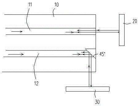
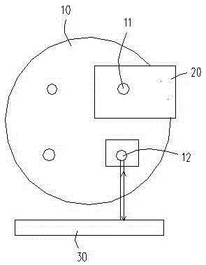
[0024] The equipment used for measuring multi-directional displacement of the multi-core optical fiber of the present invention includes a laser, a fiber grating demodulator, a fan-out device, a photodetector, a capture card, and a computer. The connected fan-out device is also an important part of the measurement system. Its function is to output each core of the connected multi-core fiber as a single-mode fiber, which is placed in a V-groove array. When installing, first couple the V-groove array composed of four single-mode fibers to the V-groove port of the fan-out device, and adjust it by using reflectivity matching gel and a manual three-dimensional translation stage. Then, use the same The method directly couples the multi-core optical fiber to the multi-core optical fiber port of the fan-out device.
[0025] In this embodiment, a four-core optical fiber is used for displacement measurement, which can measure the displacement in two and three directions. The end of the four-core optical fiber is processed by focused ion beam processing technology, and the end face of the fiber core is processed into a 45° reflecting mirror surface. When measuring the two-dimensional direction, refer to figure 1 with 2 , Take two cores of the four-core optical fiber 10 for measurement, one of the core 12 has an end face processed as a 45° reflecting mirror, and the other core 11 is left untreated. The reflection direction of the core 45° reflecting mirror It is perpendicular to the vertical direction of the end face of the multi-core optical fiber. The horizontal side end and the lower end of the quad-core optical fiber 10 are respectively placed with a mirror object 20 and a mirror object 30. The reflected light from the end faces of the core 11 and the core 12 is reflected by the mirror object 20 and the mirror object 30 The light forms interference, and the cavity length change can be demodulated according to the algorithm based on fast Fourier transform, thereby measuring the displacement in the two-dimensional direction.
[0026] When measuring the three-dimensional direction, take three cores of the four-core fiber for measurement. The end faces of two cores are processed as 45° reflecting mirrors, and the end faces of the other core are not processed, and the two cores reflect 45°. The reflection direction of the mirror is spatially vertical to the vertical direction of the end face of the multi-core optical fiber. The fan-out device connects three optical fibers to the photodetector to measure the displacement in the three-dimensional direction. The displacement can be obtained by demodulating the spectral data in each direction.
[0027] The measurement steps in the two-dimensional direction are specifically described as follows:
[0028] Step 1: Fix the processed multi-core optical fiber on the object under test, and the object under test moves along the parallel direction (front and back direction) of the end face of the multi-core optical fiber to generate displacement in the first direction;
[0029] Step 2: The reflected light from the end face of the core 11 interferes with the reflected light from the mirror object 20 to obtain the fringe contrast V of the light intensity signal, as shown in the following formula:
[0030] V = I 1 - I 2 I 1 + I 2 - - - ( 1 )
[0031] Where I 1 ,I 2 They are the light intensity of the reflected light from the end face of the multi-core fiber and the light reflected from the mirror object;
[0032] Step 3. The fringe contrast V obtained by formula (1), combined with the expression of the light intensity signal, obtains the interference signal I R , As shown in the following formula:
[0033]
[0034] Where I 0 Is the direct current component, n is the reflectivity of the fiber, generally 1.46, L is the cavity length, Is the initial phase Generally the value is π or 0;
[0035] Step 4: The interference signal I of equation (2) R Carry out standardization processing, according to the relationship between frequency and wavelength, the Bring in interference signal I R Where the spectral signal is obtained:
[0036]
[0037] Step 5. Sampling and processing the spectral signal obtained by formula (3), taking the frequency v as an independent variable, and converting the abscissa λ to Using the interpolation algorithm in MATLAB, the obtained spectral signal is resampled to the frequency domain for fast Fourier transform, and the frequency domain image of the interference signal is obtained. The cavity length is determined by the peak position of the frequency domain image, and the first peak corresponds to DC component I 0 , The second peak corresponds to the frequency f of the interference signal, and the cavity length L is calculated as shown in the following formula:
[0038] L = c f 2
[0039] Step 6, demodulate the cavity length change, and measure the displacement in the parallel direction (front and back direction) of the end face;
[0040] Step 7. The object under test moves along the vertical direction of the end face of the multi-core fiber to produce a displacement in the second direction. The reflected light of the 45° reflective mirror on the end face of the core 12 is used to interfere with the reflected light of the mirror object 30. Algorithm to measure the displacement caused by the movement in the second direction.
[0041] For the measurement and determination of landforms, you can change the mirror angle of each core in the multi-core fiber. After moving the multi-core fiber, the shape of the landform can be obtained from the interference signal through a demodulation algorithm. The demodulation algorithm described above is used to obtain each core Detect the difference of the obtained cavity length to determine the change of the topography.
[0042] The above-mentioned embodiments only describe the preferred embodiments of the present invention, and do not limit the scope of the present invention. Without departing from the design spirit of the present invention, various modifications made by those of ordinary skill in the art to the technical solutions of the present invention And improvements should fall within the protection scope determined by the claims of the present invention.