A frame-rod slow wave structure

A technology of slow-wave structure and slow-wave circuit, which is applied to the circuit components of time-of-flight tubes, etc., which can solve problems such as harmonic oscillation, limited application development, and small fundamental wave coupling impedance

Inactive Publication Date: 2017-10-20
HUAIYIN INSTITUTE OF TECHNOLOGY
View PDF5 Cites 0 Cited by
  • Summary
  • Abstract
  • Description
  • Claims
  • Application Information

AI Technical Summary

Problems solved by technology

[0007] However, the fundamental wave coupling impedance of the rectangular helical TWT is relatively small, which is easy to cause harmonic oscillation, thus limiting its application development.

Method used


Image

  • A frame-rod slow wave structure
  • A frame-rod slow wave structure
  • A frame-rod slow wave structure

Examples


Embodiment Construction

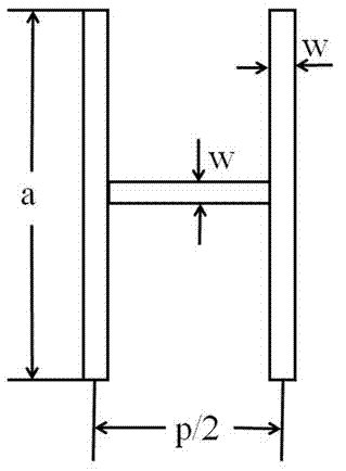
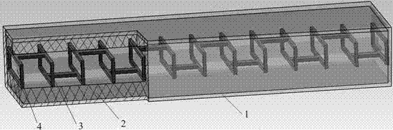
[0024] This facility mode takes the frame-rod slow-wave device working in the 50-60 GHz band with the traveling wave tube as an example: it includes a rectangular cylindrical waveguide (1), a rectangular cylindrical insulating dielectric substrate (2), a frame-rod metal The slow wave circuit (3) and the central vacuum interaction area (4); the rectangular cylindrical waveguide (1), the rectangular cylindrical insulating dielectric substrate (2), the frame-rod metal slow wave circuit (3) and the central vacuum The central axes of the interaction area (4) coincide; the rectangular cylindrical insulating dielectric substrate (2) is set in the rectangular cylindrical waveguide (1); the frame-rod metal slow wave circuit (3) is set in the rectangular cylindrical On the inner surface of the shaped insulating medium substrate (2); the frame-rod metal slow wave circuit (3) is composed of a plurality of metal wire frames with the same shape and size and connecting rods between the metal ...


PUM


Abstract

The invention provides a frame-pole slow-wave structure, belonging to the technical field of microwave vacuum devices. The structure comprises a rectangular cylindrical waveguide body (1), a rectangular cylindrical insulating dielectric substrate (2) arranged in the rectangular cylindrical waveguide body (1), a frame-pole metal slow-wave circuit (3) arranged at the surface of the rectangular cylindrical insulating dielectric substrate (2) and a center vacuum interaction region (4) enclosed in the frame-pole slow-wave circuit. The structure is characterized in that the frame-pole metal slow-wave circuit (3) is formed by connection rods among multiple metal wire frames and metal frames with the same shape and size, and the adjacent connection rods are alternately on the center connection line of a metal wire frame top side or bottom side. According to the frame-pole slow-wave structure, an existing rectangular spiral line is deformed to be the frame-pole slow-wave structure, the fundamental coupling impedance is greatly improved, the backward wave oscillation caused by harmonic wave is avoided at the same time, thus the improvement of the output power and efficiency of a traveling wave tube is facilitated, at the same time the frame-pole slow-wave structure can be realized by using the microfabrication technology, and the printed type and small targets of the traveling wave tube can be realized.

Description

technical field [0001] The patent of the invention belongs to the technical field of microwave vacuum electronics, and relates to a traveling wave tube amplifier, in particular to a frame-rod slow wave circuit structure. Background technique [0002] With the rapid development of electronic warfare and space technology in the future, more and more attention has been paid to the application of millimeter waves, and the traveling wave tube is the most important millimeter wave power source. However, in the foreseeable long period of time in the future, traveling wave tubes still have an irreplaceable status and are the most important components of millimeter wave military electronic equipment. [0003] The slow wave line is the core component of the traveling wave tube. It is the mechanism for electron injection and excitation of microwave energy in the traveling wave tube. Therefore, its high-frequency characteristics directly determine the performance of the traveling wave t...

Claims


Application Information

Patent Timeline
Patent Type & Authority Patents(China)
IPC IPC(8): H01J23/24
CPCH01J23/24H01J2223/24
Inventor 付成芳赵波居勇峰何晓凤郭新年杨定礼
Owner HUAIYIN INSTITUTE OF TECHNOLOGY
Why Eureka
Try Eureka