COT-control-based ripple-compensation-based buck circuit power management chip

A power management chip and ripple compensation technology, applied in control/regulation systems, emergency protection circuit devices, electrical components, etc., can solve problems such as increased system loss, low safety, large capacitance and resistance, and improve noise resistance ability, improve work stability, and reduce the effect of system switching loss

Active Publication Date: 2016-02-24
ZHEJIANG UNIV
View PDF5 Cites 28 Cited by
  • Summary
  • Abstract
  • Description
  • Claims
  • Application Information

AI Technical Summary

Problems solved by technology

[0005] However, in the traditional COT-controlled Buck circuit, a resistor R is directly connected in parallel at both ends of the inductor L 3 and capacitance, C 1 、C 2 The RC passive compensation method will require larger capacitors and resistors
However, if a triangular wave proportional to the inductor current is directly generated on-chip to compensate the ripple, due to the influence of the process, it cannot be guaranteed to return t

Method used


Image

  • COT-control-based ripple-compensation-based buck circuit power management chip
  • COT-control-based ripple-compensation-based buck circuit power management chip
  • COT-control-based ripple-compensation-based buck circuit power management chip

Examples


Embodiment Construction

[0034] In order to describe the present invention in more detail, the technical solution of the present invention will be described in detail below with reference to the accompanying drawings and specific embodiments.

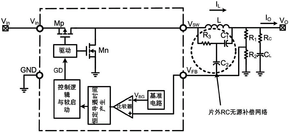
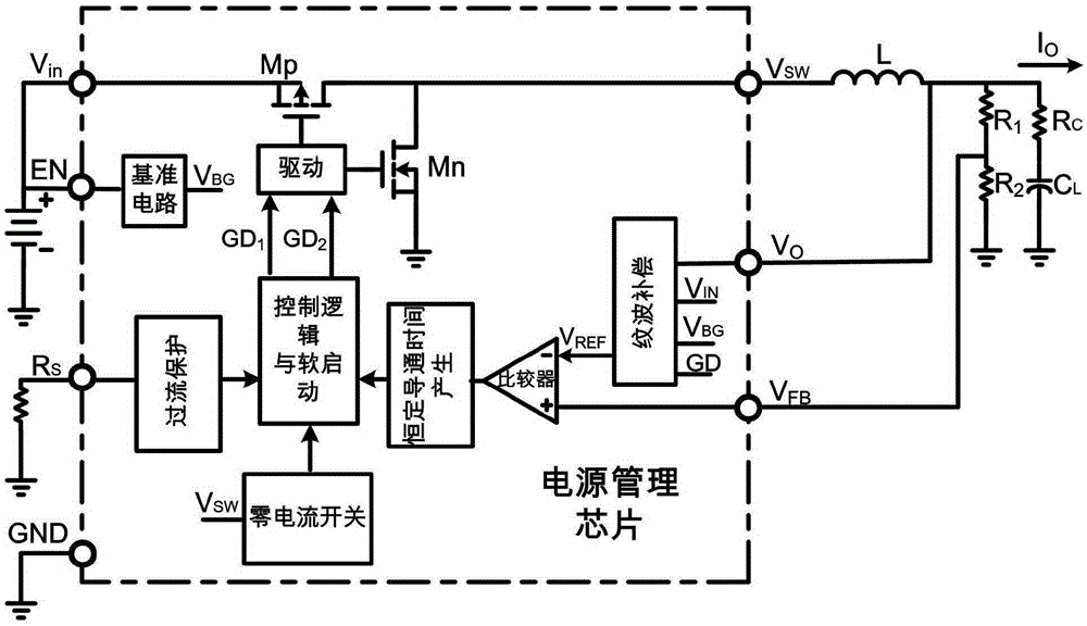
[0035] Such as image 3 As shown, the power management chip of the present invention is used in a large current buck circuit, and it is provided with a power input pin (V IN ), output voltage pin (V O ), ground pin (GND), enable pin (EN), overcurrent detection pin (R S ), feedback pin (V FB ) And switch SW pin (V SW ). The chip has a reference circuit module, an overcurrent protection module, a zero current switch module, a control logic and soft start module, a constant on-time generation module, a comparator module, a ripple compensation module, a drive module and two on-chip switching tubes Mp And Mn.

[0036] Power input pin (V IN ), access to each module in the chip to generate a power supply potential for each module in the chip to work normally. The grou...


PUM


Abstract

The invention discloses a COT-control-based ripple-compensation-based buck circuit power management chip comprising a power input pin, an output voltage pin, a grounding pin, an enabling pin, an over-current detection pin, a feedback pin and a switch SW pin. A reference circuit module, an over-current protection module, a zero-current switching module, a control logic and soft starting module, a constant conduction time generation module, a comparator module, a ripple compensation module, a drive module, and two on-chip switching tubes are arranged inside the chip. According to the power management chip provided by the invention, ripples can be superposed at the reference voltage terminal inside the chip. Compared with the traditional method superposing the ripples with the feedback voltage sampling terminal, the provided technical scheme enables the traditional COT-control-based off-chip RC passive compensation network to be reduced; and the on-chip ripple compensation module uses the active compensation way with the pseudo inductive current ramp, so that the low resistance and capacitance are used and no accumulation error of the used compensated waveform is caused.

Description

Technical field [0001] The invention belongs to the technical field of integrated circuits, and specifically relates to a Buck circuit power management chip with ripple compensation based on COT control. Background technique [0002] Power management chips are chips that manage the power consumption of each module in the system. Some power management chips will be used in switching power supply circuits. The switching power supply circuit is defined in a broad sense as a circuit that uses semiconductor power devices as switches to transform the power supply form into another form. During the transformation, it uses an automatic control closed loop to stabilize the output and has a protection link. The switching power supply circuit generally includes a control chip and peripheral circuits. Common topological structures of switching power supply circuits include: Buck, Boost, Flyback, Forward, Half Bridge and Full Bridge. Among them, the control methods of Buck circuit include: ...

Claims


Application Information

Patent Timeline
IPC IPC(8): H02M1/14H02M3/156H02H7/12
Inventor 张书瑜赵梦恋张浩洲刘胜吴晓波
Owner ZHEJIANG UNIV
Why Eureka
Try Eureka