High-precision over-temperature protection circuit
An over-temperature protection circuit, high-precision technology, applied in the direction of adjusting electrical variables, control/regulation systems, instruments, etc., can solve problems such as difficult control of over-temperature threshold, fluctuation of triode threshold value, false triggering of over-temperature protection, etc. , to achieve good market development value, good batch consistency, and simple circuit structure
- Summary
- Abstract
- Description
- Claims
- Application Information
AI Technical Summary
Problems solved by technology
Method used
Image
Examples
Embodiment 1
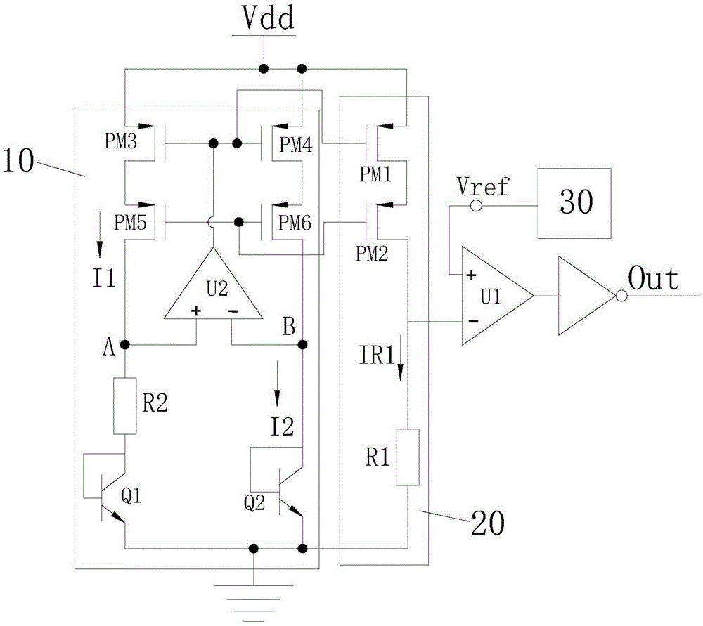
[0027] like image 3 As shown, a high-precision over-temperature protection circuit is disclosed in this embodiment, including a PTAT reference current generating circuit 10, an over-temperature comparison voltage generating circuit 20, a reference voltage generating circuit 30, and an over-temperature comparator U1. The comparison voltage generation circuit 20 and the PTAT reference current generation circuit 10 are current mirror images of each other, and the output end of the over-temperature comparison voltage generation circuit 20 and the output end of the reference voltage generation circuit 30 are respectively connected to the negative phase input end of the over-temperature comparator U1 (-) and the non-inverting input terminal (+), the output terminal of the over-temperature comparator U1 constitutes the output Out of the over-temperature protection circuit. The PTAT reference current generation circuit 10 of the present invention is used to obtain a reference current...
Embodiment 2
[0047] like Figure 4 The difference between the second embodiment shown and the first embodiment is only that: the selection of the two bipolar transistors (Q1, Q2) is different, both of which are PNP bipolar transistors, wherein the first bipolar transistor The base of Q1 is connected to its collector and then grounded, its emitter is connected to the second resistor R2, the base of the second bipolar transistor Q2 is connected to its collector and then grounded, and its emitter is connected to the drain of the sixth PMOS transistor PM6 pole. The working principle is the same as in the first embodiment, and the over-temperature contact point of the over-temperature protection is not affected by the fluctuation of the transistor manufacturing process, and the over-temperature trigger point has high precision and good batch consistency.
Embodiment 3
[0049] like Figure 5 The difference between the third embodiment shown and the first embodiment is that the structure of the PTAT reference current generation circuit 10 is different: the PTAT reference current generation circuit 10 includes a seventh PMOS transistor PM7, an eighth PMOS transistor PM8, and a ninth PMOS transistor PM9 , the tenth PMOS transistor PM10, the first NMOS transistor NM1, the second NMOS transistor NM2, the third bipolar transistor Q3, the fourth bipolar transistor Q4, the third resistor R3, the seventh PMOS transistor PM7, the eighth The sources of both PMOS transistors PM8 are connected to the power supply terminal VDD, the gates of both are connected to the gates of the first PMOS transistor PM1, and the gates of the ninth PMOS transistor PM9 and the tenth PMOS transistor PM10 are connected to The gate of the second PMOS transistor PM2, the gates of the first NMOS transistor NM1 and the second NMOS transistor NM2 are connected, the gate of the fir...
PUM
 Abstract
Description
Claims
Application Information
 - R&D
- Intellectual Property
- Life Sciences
- Materials
- Tech Scout
- Unparalleled Data Quality
- Higher Quality Content
- 60% Fewer Hallucinations
Browse by: Latest US Patents, China's latest patents, Technical Efficacy Thesaurus, Application Domain, Technology Topic, Popular Technical Reports.
© 2025 PatSnap. All rights reserved.Legal|Privacy policy|Modern Slavery Act Transparency Statement|Sitemap|About US| Contact US: help@patsnap.com


