Wire harness adhesive tape winding machine

A technology of winding machine and winding mechanism, applied in the direction of manufacturing wire harnesses, etc., can solve the problems of uneven coverage, abrasion of wire harness products, easy wrinkling of tapes, etc., to achieve good economic benefits, improve production efficiency, and reduce labor intensity.

Inactive Publication Date: 2016-03-02
SHANGHAI MENSA AUTO PARTS MFG
View PDF7 Cites 13 Cited by
  • Summary
  • Abstract
  • Description
  • Claims
  • Application Information

AI Technical Summary

Problems solved by technology

[0002] At present, the structure of the existing wire harness tape winding equipment mainly includes a wire harness drag shaft, a rotating winding device, a tape holder and a foot switch. When working, the wire harness is pulled by the wire harness supporting shaft in the rotating winding device with the cooperation of both hands to complete the entire wire harness. During the winding and wrapping process, the foot switch controls the operation and stop of the whole device. This type of semi-automatic wire harness wrapping equipment uses a fixed tape position and hand-controlled wiring harness. However, this structure of wire harness tape winding equipment has the following problems. Point defects: 1. During production and processing, the wire harness is controlled by both hands to pull. During the process, the wire harness product will be subject to certain external wear, or it will be wound and deformed after pulling. It lacks sliding wear protection and pulling for the wire harness. Deformation protection measures, when the outer diameter of the wire harness product is too small, the appearance after prod

Method used


Image

  • Wire harness adhesive tape winding machine
  • Wire harness adhesive tape winding machine
  • Wire harness adhesive tape winding machine

Examples


Embodiment Construction

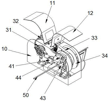
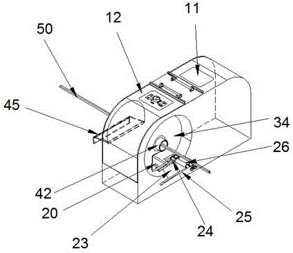
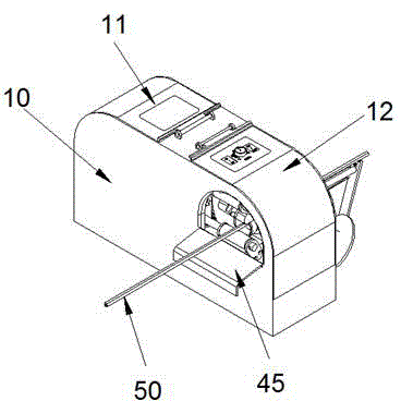
[0030] Such as figure 1 As shown, a wire harness tape winding machine is composed of a body 10, a tape winding mechanism, a tape winding drive mechanism, a wire harness traction mechanism and a wire harness 50, wherein a front cover 12 and a rear cover 11 are opened on the top of the body 10 housing, and the tape winding institutions (see figure 2 ) is made up of a tape stand base 20, a tape shaft 23 connected to the tape stand base 20, a short support 24, a long support 25, and a pair of rollers 26 arranged between the short support 24 and the long support 25; the tape winding drive mechanism is composed of The first motor 31, the driving pulley 32 driven by the first motor 31 to rotate, the belt 33 and the driven pulley 34 that carries out the belt transmission by the belt 33 are composed; Drive the dynamic pressure spool frame 43 for rotational movement, the constant pressure spool frame 44 corresponding to the position of the dynamic pressure spool frame 43, the wire pas...


PUM


Abstract

The invention discloses a wire harness adhesive tape winding machine. The wire harness adhesive tape winding machine comprises the components of a body, an adhesive tape winding mechanism which is arranged on the body, an adhesive tape winding driving mechanism which drives the adhesive tape winding mechanism to operate, and a wire harness traction mechanism. The adhesive tape winding mechanism comprises an adhesive tape rack base, an adhesive tape shaft, an adhesive tape guiding bracket and a roller pair. The adhesive tape winding driving mechanism comprises a first motor and a belt conveying device. The wire harness traction mechanism comprises a second motor, a wire gland, a dynamic pressure bobbin and a static pressure bobbin. The wire harness is fed between the static pressure bobbin and the dynamic pressure bobbin and is output in the wire gland. The wire harness adhesive tape winding machine is suitable for performing wire harness packaging through diversified adhesive tapes and effectively prevents wire harness scratch. Furthermore a suitable wire gland is correspondingly changed according to the outer diameter of the packaged wire harness. The wire harness adhesive tape winding machine has advantages of effectively controlling movement range of the wire harness, reducing vibration, realizing adjustable and controllable winding process, replacing traditional semi-automatic winding operation, reducing labor intensity, improving production efficiency and obtaining high economic benefit.

Description

technical field [0001] The invention relates to tape winding equipment, in particular to a wire harness tape winding machine for winding wire harnesses with tape. Background technique [0002] At present, the structure of the existing wire harness tape winding equipment mainly includes a wire harness drag shaft, a rotating winding device, a tape holder and a foot switch. When working, the wire harness is pulled by the wire harness supporting shaft in the rotating winding device with the cooperation of both hands to complete the entire wire harness. During the winding and wrapping process, the foot switch controls the operation and stop of the whole device. This type of semi-automatic wire harness wrapping equipment uses a fixed tape position and hand-controlled wiring harness. However, this structure of wire harness tape winding equipment has the following problems. Point defects: 1. During production and processing, the wire harness is controlled by both hands to pull. Duri...

Claims


Application Information

Patent Timeline
IPC IPC(8): H01B13/012
Inventor 张治国
Owner SHANGHAI MENSA AUTO PARTS MFG
Why Eureka
Try Eureka