

High-efficiency energy-saving current amplifier
A current amplifier, high-efficiency and energy-saving technology, applied in the direction of power amplifiers, can solve the problems of low precision, small maximum output current, large power loss, etc., to achieve the effect of improving sampling accuracy, reducing power loss, and increasing the maximum output current
- Summary
- Abstract
- Description
- Claims
- Application Information
AI Technical Summary
Problems solved by technology
Method used
Image

Examples
Embodiment Construction
[0016] The present invention provides a high-efficiency energy-saving current amplifier. The present invention will be further described below in conjunction with the description of the drawings and specific implementation methods.
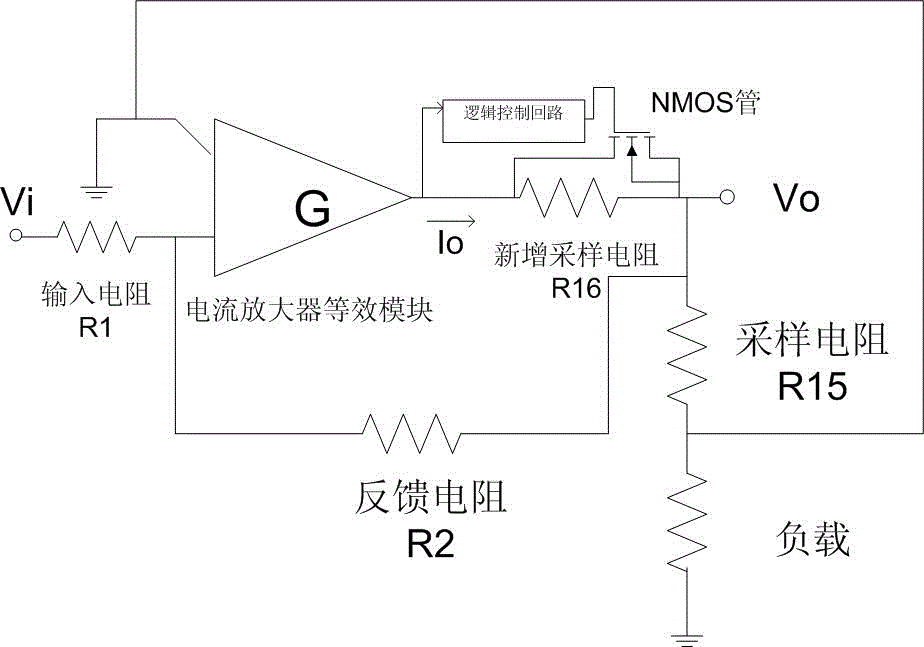
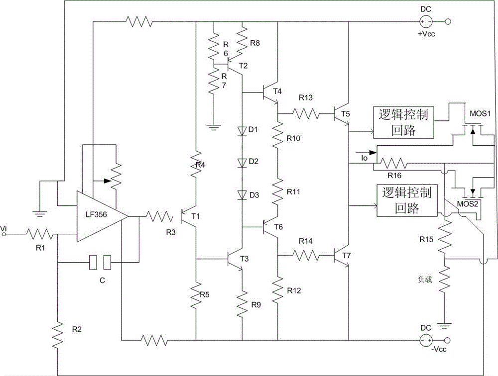
[0017] refer to figure 1 , figure 2 As shown, the high-efficiency and energy-saving current amplifier is used in the relay protection tester, and is composed of an input stage, a driving stage, and an output stage. The input stage is composed of LF356 operational amplifier, the driving stage is composed of transistors T1 and T3, and the output stage is composed of complementary Darlington circuit. When the collector of T3 is in the positive half cycle, the transistors T4 and T5 are turned on. When the collector of T3 is in the negative half cycle, the transistors T6 and T7 are turned on. Transistor T3 drives transistors T4 and T6, and transistors T4 and T6 drive transistors T5 and T7 respectively.
[0018] When the current output by T5 and T7...
PUM
 Abstract
Description
Claims
Application Information