A high pressure and large ratio flow regulating valve

A technology of flow regulating valve and large variable ratio, which is applied in the direction of valve lift, valve details, valve device, etc., which can solve the problems of non-replaceable throttling orifice plate, inaccurate flow conditions, complicated control, etc., and achieve light weight and simple control Convenience and high adjustment accuracy

Active Publication Date: 2017-06-13
XIAN AEROSPACE PROPULSION INST
View PDF4 Cites 3 Cited by
  • Summary
  • Abstract
  • Description
  • Claims
  • Application Information

AI Technical Summary

Problems solved by technology

[0004] In order to solve the technical problems of existing single-element flow regulating valves that cannot replace the throttling orifice plate, the flow conditions are inaccurate, and the control is relatively complicated, the present invention proposes a simple control, high adjustment accuracy, large flow ratio, and adaptable to different working conditions. conditional flow control valve

Method used


Image

  • A high pressure and large ratio flow regulating valve
  • A high pressure and large ratio flow regulating valve
  • A high pressure and large ratio flow regulating valve

Examples


Embodiment Construction

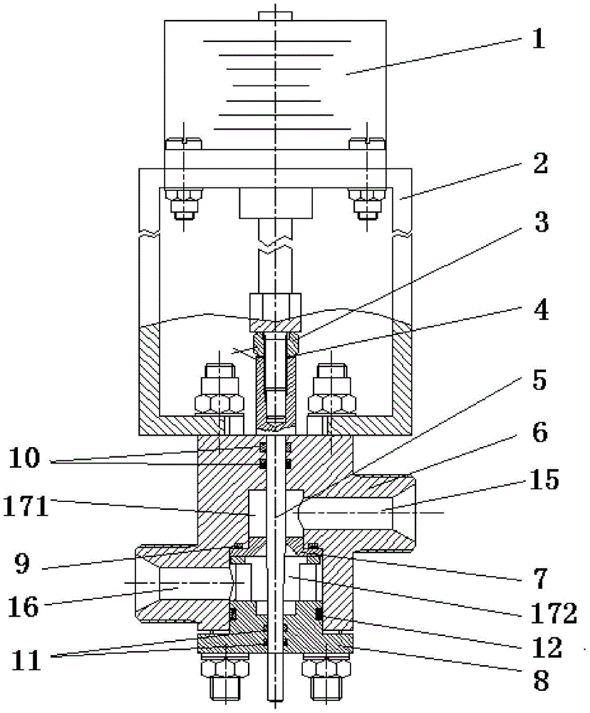
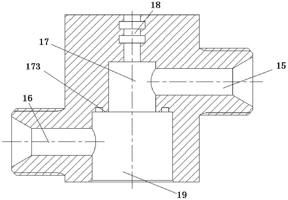
[0038] Such as figure 1As shown, the high pressure and large variable ratio flow regulating valve of the present invention consists of a linear stepper motor 1, a frame 2, a lock nut 3, a saddle gasket 4, an adjusting rod 5, a housing 6, a throttle orifice 7, a pressure plate 8. Composed of rubber O-rings 9 and 10. The inlet passage 15 and the outlet passage 16 are connected by a liquid chamber 17 arranged in the housing, and the throttle orifice 7 is arranged in the liquid chamber 17, and the throttle orifice 7 is provided with a connection between the inlet passage 15 and the outlet passage 16. The throttle hole 71; the adjusting rod 5 is coaxial with the output shaft of the linear stepping motor 1, and the adjusting rod 5 is divided into a fastening part 51 and an adjusting part 52, and the fastening part 51 is fixedly connected with the output shaft of the linear stepping motor 1 , the diameter of the adjustment part 52 is variable, and the housing at one end of the throt...


PUM


Abstract

The invention relates to a high-pressure large-transformation-ratio flow regulating valve which is composed of a linear stepping motor, a regulating rod, a machine frame, a throttling pore plate, a saddle-shaped gasket, a lock nut, a shell, a pressing plate and the like. A driving mechanism comprises the linear stepping motor. A regulation part is composed of the regulating rod and the throttling pore plate. The linear stepping motor is connected with the shell through the machine frame. A shaft of the linear stepping motor and the regulating rod are connected together and locked tightly through the saddle-shaped gasket and the lock nut. The throttling pore plate is installed inside the shell in a pressed mode through the pressing plate. The throttling pore plates with different pore diameters can be replaced according to different flow regulation ranges. In order to guarantee the sealing performance under high pressure, motive seal positions of external leakage are sealed through two O-shaped rubber rings. In the flow regulation process, a control signal is input to the linear stepping motor, the linear stepping motor drives a regulation element to move upwards and downwards, the flow area of the throttling pore plate is changed, and accordingly flow regulation is achieved.

Description

technical field [0001] The invention relates to a flow regulating valve with high pressure and large variable ratio, which can be adapted to various liquid rocket engines that need to regulate the flow. Background technique [0002] The variable thrust rocket engine has the advantage of adjustable thrust, which is the best choice for some spacecraft systems. For example, the main engine SSME of the space shuttle in the United States can change its thrust within the range of 50% to 109% of the rated thrust, and the main engine of my country's CE-3 Lunar also has a thrust ratio of 5:1. In variable-thrust liquid rocket engines, it is often necessary to use a flow regulating valve to change the flow of propellant during the working process of the liquid rocket engine. [0003] Existing single-element flow regulating valves do not have the function of changing the throttle orifice to adjust the flow range. Most of the flow regulating valves have a disproportionate displacement o...

Claims


Application Information

Patent Timeline
Patent Type & Authority Patents(China)
IPC IPC(8): F02K9/58F16K1/00F16K1/32F16K31/04
CPCF02K9/58F16K1/00F16K1/32F16K31/04
Inventor 祁增强袁洪滨蔡德慧陈展王可立赫伟涛
Owner XIAN AEROSPACE PROPULSION INST
Why Eureka
Try Eureka