Energy saving fan component

A component and fan technology, applied in pump components, mechanical equipment, machines/engines, etc., can solve the problems of fan wind pressure attenuation, low fan efficiency, low speed, etc., to reduce wind resistance and wind flow disturbance, and control speed accuracy. The effect of high and wind pressure will not be attenuated

Inactive Publication Date: 2016-03-09
万鹏昌
View PDF6 Cites 4 Cited by
  • Summary
  • Abstract
  • Description
  • Claims
  • Application Information

AI Technical Summary

Problems solved by technology

[0003] 1. The air compressor solution is used. In order to maintain the air pressure, it needs to be turned on even when it is not working, and the waste of electric energy is serious.
Moreover, during the air compression process, the water vapor in the air will condense into water droplets, which cannot be used in special occasions.
[0004] 2. The fan assembly powered by an induction motor whose speed is controlled by a frequency converter needs to obtain high-speed air output, so the motor speed is very high, and since the small induction motor is a relatively traditional type of motor, there is a volume in the case of high speed Large, low efficiency, severe heat generation, must be equipped with cooling devices and other shortcomings, the energy saving effect is not ideal
In addition, the impeller of the induction motor fan component with variable speed frequency converter adopts the front semi-open impeller, and the overall efficiency of the fan is low
[0005] 3. The method of increasing the wind pressure by connecting small heat dissipation fans in series, generally in order to increase the wind pressure, about 10 heat dissipation fans are connected in series, and each fan works independently, the motor itself has low efficiency, low speed, and low wind pressure. The fan efficiency of the solution is also low, and after the fan blades adhere to dust and other impurities, the speed will decrease, and ...

Method used


Image

  • Energy saving fan component
  • Energy saving fan component
  • Energy saving fan component

Examples


Embodiment Construction

[0026] In order to make the objectives, technical solutions and advantages of the present invention clearer, the present invention will be further described in detail below with reference to the accompanying drawings and embodiments. It should be understood that the specific embodiments described herein are only used to explain the present invention, but not to limit the present invention.

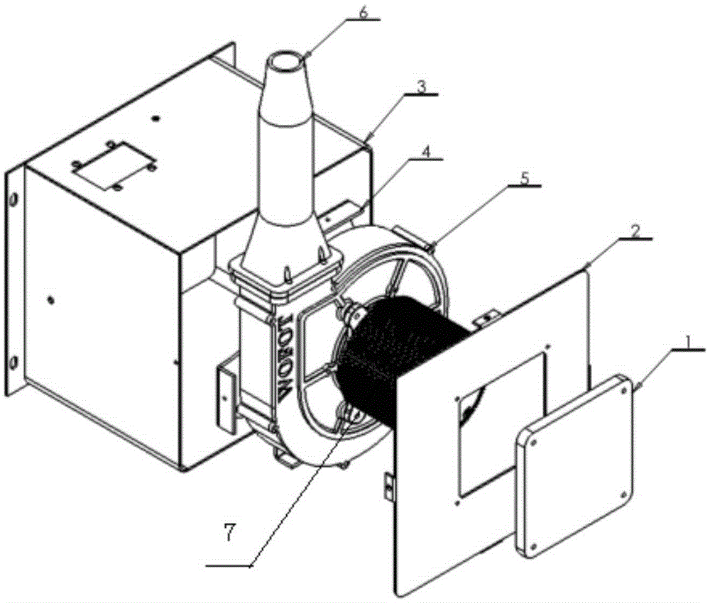
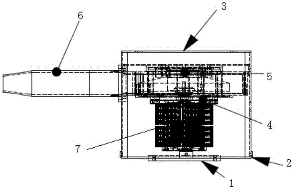
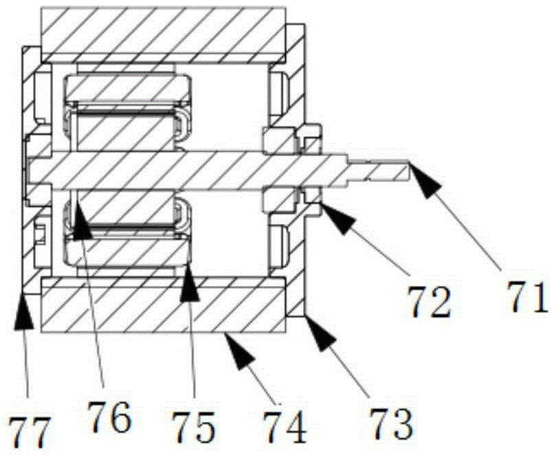
[0027] see Figure 1a , Figure 1b , Figure 2a , Figure 2b , Figure 3a and Figure 3b , Figure 1a , Figure 1b is a schematic structural diagram of the energy-saving fan assembly provided by the embodiment of the present invention, Figure 2a , Figure 2b is a schematic structural diagram of a brushless DC motor provided by an embodiment of the present invention; Figure 3a , Figure 3b It is a connection diagram of the brushless DC motor and the volute centrifugal fan provided by the embodiment of the present invention.

[0028] The embodiment of the present invention provide...


PUM


Abstract

The invention provides an energy saving fan component. The energy saving fan component comprises a shell provided with a volute centrifugal fan inside, and further comprises a brushless direct-current motor, wherein cooling ribs are arranged on the shell of the motor; and when the brushless direct-current motor rotates, air exhausted by a multi-wing closed impeller penetrates through a filter component and flows through the cooling ribs of the brushless direct-current motor to enter a volute, and is blown out from air pipes. The energy saving fan component has the following beneficial effects: the motor in the fan component adopts the brushless direct-current motor specially matched with the volute impeller; the structure is simple; the rotating speed control precision is high; and the advantages of strong interference resistance and high reliability are achieved. The matched volute centrifugal fan impeller adopts the multi-wing closed impeller; blades of the impeller have special radians to reduce the air resistance and the airflow disturbance; the impeller fits a matched volute component; the whole efficiency of the fan is higher; and the energy is saved by more than 20%. Compared with a mode of serial connection of a cooling fan, the efficiency of the fan is higher by more than 50%, the service life of the fan is long, and the air pressure magnitude is adjustable.

Description

technical field [0001] The invention relates to the technical field of fans, in particular to an energy-saving fan assembly. Background technique [0002] Currently used in CNC processing, stamping processing, grinding, air drying, air showers, etc. where high-pressure blowing equipment is required, the main solution is to use the original air compressor, and the fan assembly powered by an induction motor with frequency conversion and speed regulation by a frequency converter , and the way of connecting small cooling fans in series to increase wind pressure. [0003] 1. Using the air compressor scheme, in order to maintain the air pressure, it needs to be turned on all the time even when it is not working, and the electric energy is wasted seriously. Moreover, in the process of air compression, the water vapor in the air will condense into water droplets, which cannot be used in special occasions. [0004] 2. The fan assembly powered by the induction motor controlled by th...

Claims


Application Information

Patent Timeline
IPC IPC(8): F04D25/08F04D29/08F04D29/10F04D29/28F04D29/30F04D29/42F04D29/58F04D29/70
CPCF04D25/082F04D29/083F04D29/102F04D29/281F04D29/30F04D29/4213F04D29/4233F04D29/5806F04D29/582F04D29/703
Inventor 万鹏昌
Owner 万鹏昌
Why Eureka
Try Eureka