
Permanent magnet and magnetic apparatus for nuclear magnetic resonance imaging system

A technology of magnets and permanent magnets, applied in the direction of measuring devices, permanent magnets, and measuring magnetic variables, etc., can solve the problems of bulkiness, low magnetic field strength, and increased cost of permanent magnets, and achieve the goal of reducing costs, increasing magnetic field strength, and reducing difficulty Effect

Active Publication Date: 2016-03-09
NEUSOFT MEDICAL SYST CO LTD
View PDF11 Cites 15 Cited by
  • Summary
  • Abstract
  • Description
  • Claims
  • Application Information

AI Technical Summary

Problems solved by technology

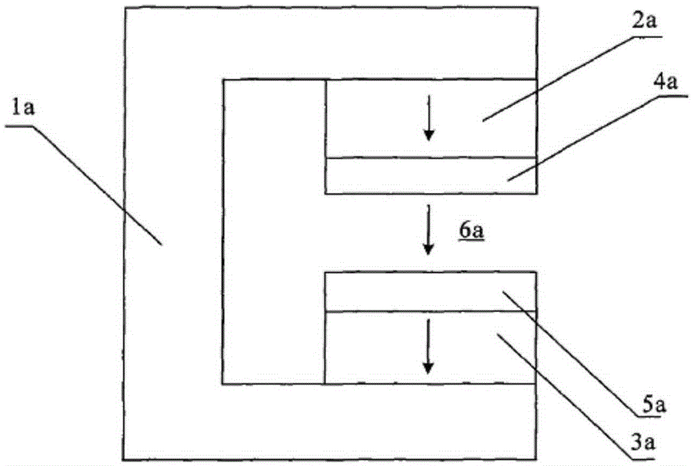
The magnetic field strength in the working area of ​​the magnet device is low, generally 0.4 Tesla or below. To increase the magnetic field strength, a large amount of permanent magnet materials will be used, which greatly increases the cost of permanent magnets used in MRI. and it's bulky

Method used


Image

  • Permanent magnet and magnetic apparatus for nuclear magnetic resonance imaging system
  • Permanent magnet and magnetic apparatus for nuclear magnetic resonance imaging system
  • Permanent magnet and magnetic apparatus for nuclear magnetic resonance imaging system

Examples


Embodiment Construction

[0043] In order to make the purpose, technical solutions and advantages of the embodiments of the present invention clearer, the technical solutions in the embodiments of the present invention will be clearly and completely described below in conjunction with the drawings in the embodiments of the present invention. Obviously, the described embodiments It is a part of embodiments of the present invention, but not all embodiments. Based on the embodiments of the present invention, all other embodiments obtained by persons of ordinary skill in the art without making creative efforts belong to the protection scope of the present invention.

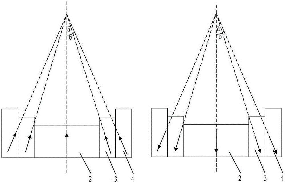
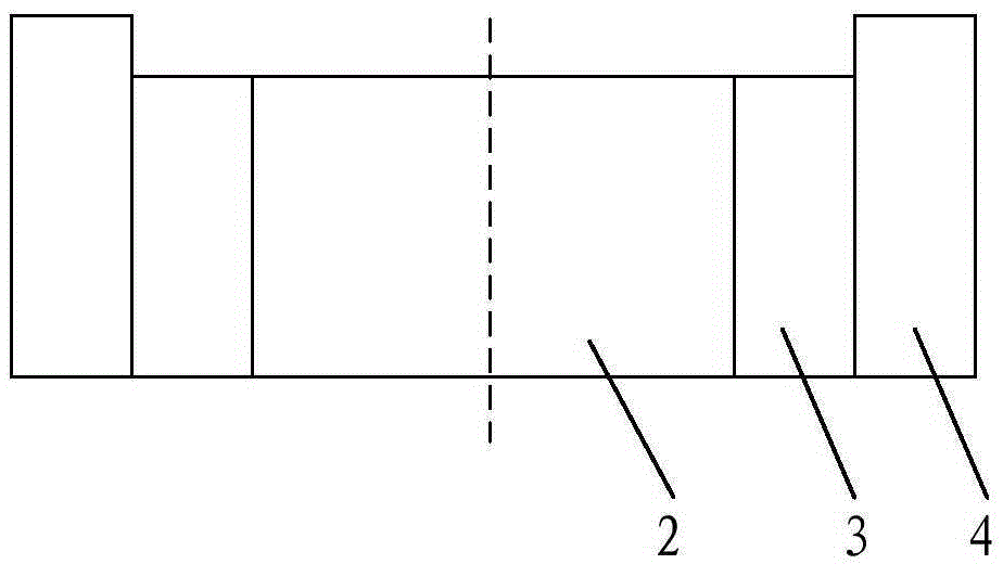
[0044] see Figure 2A , Figure 2B and Figure 2C , is a side view of the permanent magnet provided by the embodiment of the present invention. The permanent magnet includes: a cylindrical inner magnet 2 made of permanent magnetic material, a first cylindrical side magnet 3 and a second cylindrical side magnet 4 . Wherein, the permanent m...


PUM


Abstract

The invention discloses a permanent magnet. The permanent magnet comprises a columnar inner magnet, a first columnar side magnet and a second columnar side magnet that are made from a permanent magnetic material; the first columnar side magnet is coaxially arranged on the external of the columnar inner magnet; the second columnar side magnet is coaxially arranged on the external of the first columnar inner magnet; the heights of the columnar inner magnet, the first columnar side magnet and the second columnar side magnet are entirely or partially different, and an approximate concave curved surface is formed; the magnetization direction of the columnar inner magnet is an axial direction; a first angle is formed between the magnetization direction of the first columnar side magnet and the axial direction; a second angle is formed between the magnetization direction of the second columnar side magnet and the axial direction; and the second angle is greater than or equal to the first angle. The invention also discloses a magnetic apparatus used for a nuclear magnetic resonance imaging system.

Description

technical field [0001] The invention relates to the technical field of permanent magnets, in particular to a permanent magnet and a magnet device used in a nuclear magnetic resonance imaging system. Background technique [0002] Magnetic Resonance Imaging, also known as Magnetic Resonance Imaging (MRI for short), is a technology that uses the signal generated by the resonance of atomic nuclei in a magnetic field for image reconstruction. Nuclear Magnetic Resonance technology is not only used in physics and chemistry, but also in the field of clinical medicine. . [0003] MRI equipment can generally be divided into three parts: magnet system, nuclear magnetic resonance spectrometer and image processing and display system. Among them, the magnet system is composed of a magnet device and a coil. The magnet device is the main component of the MRI equipment, which determines the image quality and work efficiency of the MRI equipment. At the same time, the magnet device is also t...

Claims


Application Information

Patent Timeline
Patent Type & Authority Applications(China)
IPC IPC(8): H01F7/02G01R33/383
Inventor 朱妍胡红兵
Owner NEUSOFT MEDICAL SYST CO LTD
Learn More