
A kind of catalytic cracking method

A technology of catalytic cracking and catalyst regeneration, which is applied in the direction of refining and cracking process only in multi-stage series, can solve the problems of high energy consumption and low efficiency of catalytic upgrading of gasoline, and achieve the purpose of suppressing secondary reactions, avoiding gasoline condensation and Effect of regasification process and property improvement

Active Publication Date: 2017-07-14
SINOPEC LUOYANG PETROCHEM ENG CORP +1
View PDF4 Cites 0 Cited by
  • Summary
  • Abstract
  • Description
  • Claims
  • Application Information

AI Technical Summary

Problems solved by technology

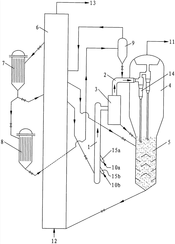
[0006] The purpose of the present invention is to provide a kind of catalytic cracking method, to solve the secondary reaction of the cracking product that existing catalytic cracking technology respectively exists and has not been effectively controlled (due to the regional space that the oil agent contacts is relatively large or the second stage promotes A large number of secondary reactions of cracking products will inevitably occur in the tube), gasoline catalytic upgrading efficiency is low (because the gasoline upgrading process is adversely affected by the secondary reaction of heavy oil and diesel components in the same reactor), The upgrading process of catalytic gasoline has high energy consumption (due to the large amount of low-temperature heat generated during the condensation and regasification of gasoline) and other issues

Method used


Image

  • A kind of catalytic cracking method
  • A kind of catalytic cracking method
  • A kind of catalytic cracking method

Examples


Embodiment 1

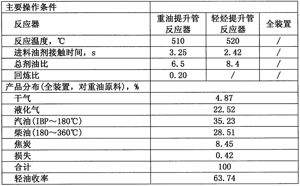
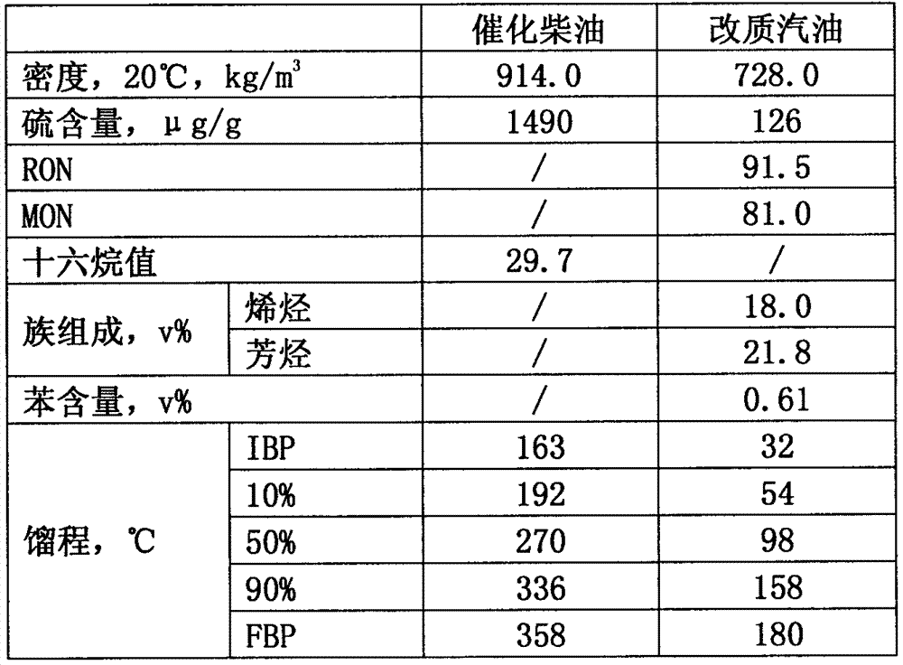
[0042] The main operating conditions and product distribution of Example 1 are shown in Table 4, and the main properties of the liquid product are shown in Table 5. The main operating conditions and product distribution of Example 2 are shown in Table 6, and the main properties of the liquid product are shown in Table 7. The main operating conditions and product distribution of Example 3 are shown in Table 8, and the main properties of the liquid product are shown in Table 9. The main operating conditions and product distribution of Example 4 are shown in Table 10, and the main properties of the liquid product are shown in Table 11. The main operating conditions and product distribution of Example 5 are shown in Table 12, and the main properties of the liquid product are shown in Table 13.

[0043] Table 1 Properties of heavy oil raw materials (comparative examples, examples 1-5)

[0044] Heavy Oil Raw Materials Daqing Atmospheric Residue Density, 20℃, kg·m ...


PUM


Abstract

The invention discloses a catalytic cracking method in the petrochemical industry. The method includes: the reaction is carried out in two stages, the first stage reaction is heavy oil catalytic cracking reaction carried out in the first tubular reactor, the first stage reaction is carried out after gas-solid separation, and the first stage reaction oil gas directly undergoes the second stage reaction, that is, enters the second tube Catalytic reforming reaction of gasoline with a reaction temperature of 430-460°C in a type reactor. The first-stage spent catalyst and the second-stage spent catalyst are stripped and then enter the regenerator for coke regeneration. Part of the regenerated catalyst in the regenerator is directly returned to the first tubular reactor to participate in the first-stage reaction; part of the regenerated catalyst enters the primary regenerated catalyst cooler for primary cooling, and then enters the secondary regenerated catalyst cooler for secondary cooling. After reaching 400-450°C, return to the second tubular reactor to participate in the second-stage reaction. The invention can be used for catalytic cracking of heavy oil and catalytic upgrading of gasoline.

Description

technical field [0001] The invention relates to a catalytic cracking method in the petrochemical industry. Background technique [0002] The traditional catalytic cracking technology used in the petrochemical industry generally has the following disadvantages: First, the oil agent contact time for heavy oil reaction is long (generally about 4s, s is seconds), which increases the conversion rate of heavy oil and also aggravates The secondary reaction of cracking products is prevented, so that the yield of cracked gas (including dry gas and liquefied gas) and coke is higher, and the yield of gasoline and diesel fractions is lower; it also makes the quality of catalytic diesel oil poor, which is not suitable for use as Vehicle fuel blending components. Second, there is a lack of catalytic upgrading measures for gasoline, which has high olefin content and low quality. Over the years, research institutions at home and abroad have done a lot of research work on overcoming the sh...

Claims


Application Information

Patent Timeline
Patent Type & Authority Patents(China)
IPC IPC(8): C10G55/06
Inventor 陈曼桥武立宪王文柯樊麦跃汤海涛
Owner SINOPEC LUOYANG PETROCHEM ENG CORP
Learn More