A Micro Dispersed Combustion Device for Micro-thermo-photovoltaic System

A micro-thermal photoelectric and combustion device technology, applied in burners, burners, combustion types, etc., can solve the problems of poor heat exchange between flue gas and wall surface, large space occupied by intake air premixing, and short gas residence time, etc. Achieve the effect of reducing external premixing devices, reducing ignition difficulty, uniform flame and temperature distribution

Inactive Publication Date: 2017-09-26
CHONGQING UNIV
View PDF5 Cites 0 Cited by
  • Summary
  • Abstract
  • Description
  • Claims
  • Application Information

AI Technical Summary

Problems solved by technology

[0003] In view of the deficiencies in the above existing technologies, such as the low and uneven wall temperature of the micro-combustor in the micro-thermal photoelectric system, the large space occupied by the intake air premix, the premix preheating effect is poor and the intake air temperature is low, and the intake air area small, the residence time of the gas in the device is short, and the heat exchange effect between the flue gas and the wall surface is poor.

Method used


Image

  • A Micro Dispersed Combustion Device for Micro-thermo-photovoltaic System
  • A Micro Dispersed Combustion Device for Micro-thermo-photovoltaic System
  • A Micro Dispersed Combustion Device for Micro-thermo-photovoltaic System

Examples


Embodiment Construction

[0026] The present invention will be described in further detail below in conjunction with the accompanying drawings and specific embodiments.

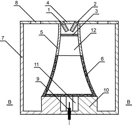
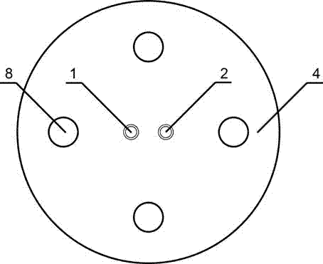
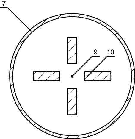
[0027] Such as figure 1 , figure 2 with image 3 As shown, a micro-dispersed combustion device for a micro-thermophotoelectric system includes an ignition device 9 , an outer sleeve 7 , an inner sleeve 5 and an upper panel 4 . The inner sleeve 5 is located in the outer sleeve 7 , and the inner sleeve 5 and the outer sleeve 7 are arranged coaxially. The bottom end of the outer sleeve 7 is provided with a sealing plate, and the upper panel 4 is arranged on the top end of the outer sleeve 7 and sealed with the outer sleeve 7 . The inner sleeve 5 has a trumpet-like structure with a large lower end. The lower end of the inner sleeve 5 is provided with a porous bottom plate. The lower peripheral wall of the inner sleeve 5 is a porous wall 6 . Inside the inner sleeve 5 is a preheating and premixing chamber 12, and a combustion chamber 1...


PUM


Abstract

The invention provides a micro diffuse type combustion apparatus for a micro-thermphotoelectric system. The micro diffuse type combustion apparatus for the micro-thermphotoelectric system comprises an ignition device, an external sleeve, an internal sleeve and an upper panel, wherein the internal sleeve is positioned in the external sleeve; the upper panel is arranged at the top end of the external sleeve; the internal sleeve is a flared structure with big lower end; the lower end of the internal sleeve is provided with a porous bottom plate; the circumferential wall of the lower part of the internal sleeve; the interior of the internal sleeve is a preheating premixing chamber; a combustion chamber is formed between the internal sleeve and the external sleeve; the preheating premixing chamber is communicated with the combustion chamber through a porous wall and the porous bottom plate; and a gas exhaust opening, an air inlet and a fuel gas inlet are formed in the upper panel. According to the invention, as air enters the porous material from various surfaces, a temperature field is uniform and the combustion is enhanced to increase the device power; through the adoption of special combustion chamber wall surface design, heat obtained by the whole wall surface is much and uniform; the micro diffuse type combustion apparatus can stably respond to fine air inlet pulsation and combustion pulsation; and meanwhile, through the adoption of the porous material with reducing aperture, tempering and backflow problems of the porous material are also avoided.

Description

technical field [0001] The invention relates to a micro-combustor suitable for a micro-thermo-photoelectric system and a micro-thermo-electric system, in particular to a micro-diffused combustion device for a micro-thermo-photoelectric system with a preheating and premixing chamber and a combustion chamber expanding gradually at the same time. Background technique [0002] Micro-scale combustion is proposed with the development of MEMS (micro-electromechanical system) technology, and its combustion is usually below 1cm 3 occurs within the volume. The power generation principle of micro-scale combustion is: micro-scale burners produce high-temperature flue gas to drive heat engines to generate power, or obtain electricity through direct conversion of thermoelectric materials and generate electricity through photoelectric materials. The application fields involve micro-aircraft, micro-satellite propulsion systems, and military individual combat. And many other aspects. Compa...

Claims


Application Information

Patent Timeline
Patent Type & Authority Patents(China)
IPC IPC(8): F23D14/02F23D14/62F23D14/66F23D14/46
CPCF23D14/02F23D14/46F23D14/62F23D14/66F23D2203/007F23D2206/00F23D2212/00Y02E20/34
Inventor 闫云飞吴刚娥尹昊文张力翟越冯帅蒲舸杨仲卿唐强陈艳容冉景煜丁林
Owner CHONGQING UNIV
Why Eureka
Try Eureka