Combined layout structure of flue gas system with six outlets of dust collector and double row induced draft fan

A technology for arranging structure and induced draft fan, which is applied in the direction of induced draft, exhaust gas device, lighting and heating equipment, etc., can solve the problems of difficulty in making full use of space, unreasonable equipment layout, large layout area, etc., and saves the length of pipes. , The effect of optimizing the flue gas flow field and reducing the footprint

Active Publication Date: 2018-06-05
CHINA ENERGY ENG GRP GUANGDONG ELECTRIC POWER DESIGN INST CO LTD
View PDF7 Cites 0 Cited by
  • Summary
  • Abstract
  • Description
  • Claims
  • Application Information

AI Technical Summary

Problems solved by technology

[0005] Based on this, aiming at the unreasonable layout of the above-mentioned traditional equipment after the dust collector, it is difficult to make full use of the space everywhere, so that the layout of the equipment after the dust collector occupies a large area, the flue is long, and the resistance is large. The present invention proposes a dust removal Combined layout structure of the flue gas system behind the six outlets of the device and the double-row induced draft fan

Method used


Image

  • Combined layout structure of flue gas system with six outlets of dust collector and double row induced draft fan
  • Combined layout structure of flue gas system with six outlets of dust collector and double row induced draft fan
  • Combined layout structure of flue gas system with six outlets of dust collector and double row induced draft fan

Examples


Embodiment Construction

[0027] Embodiments of the present invention will be described in detail below in conjunction with the accompanying drawings.

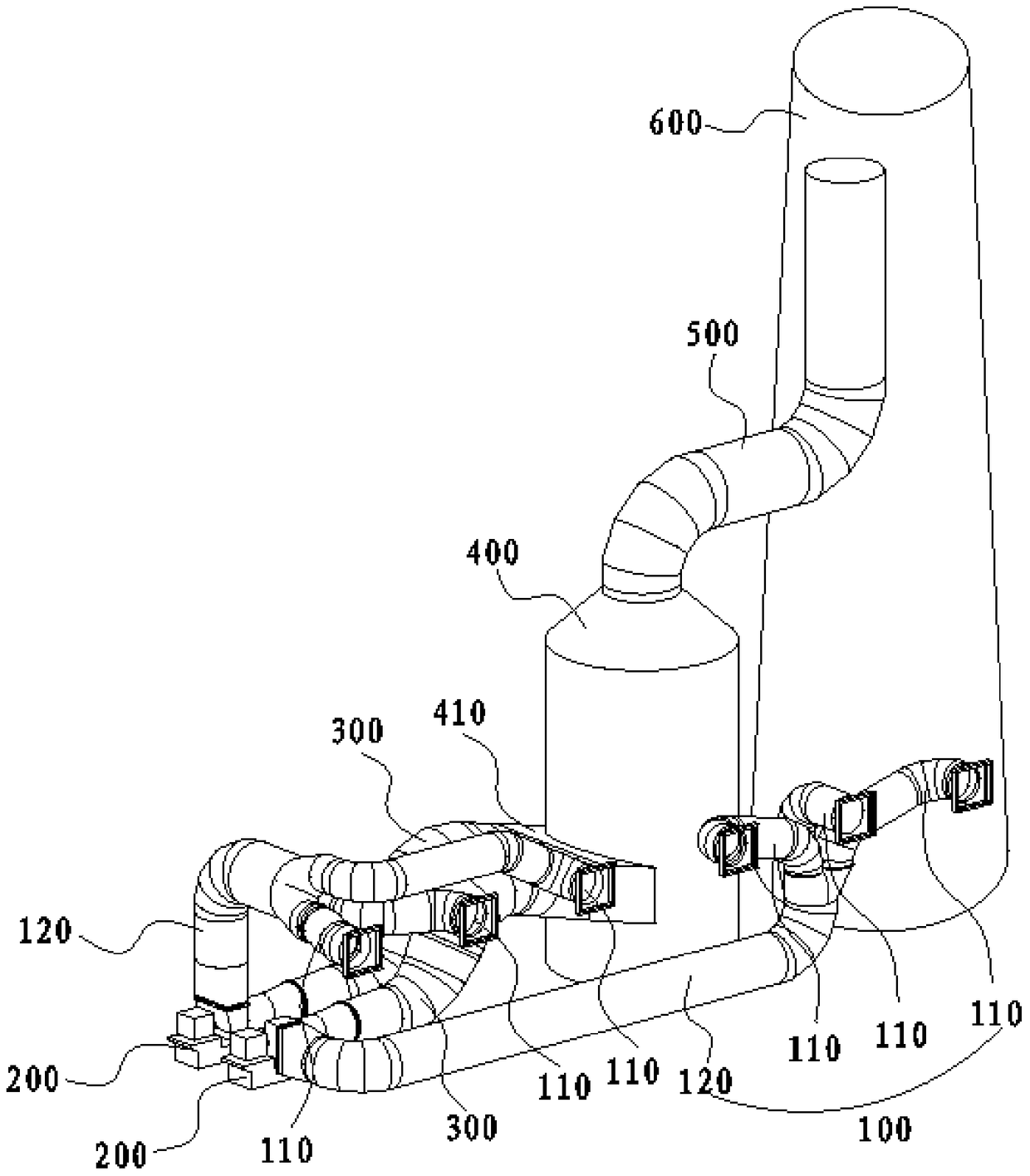
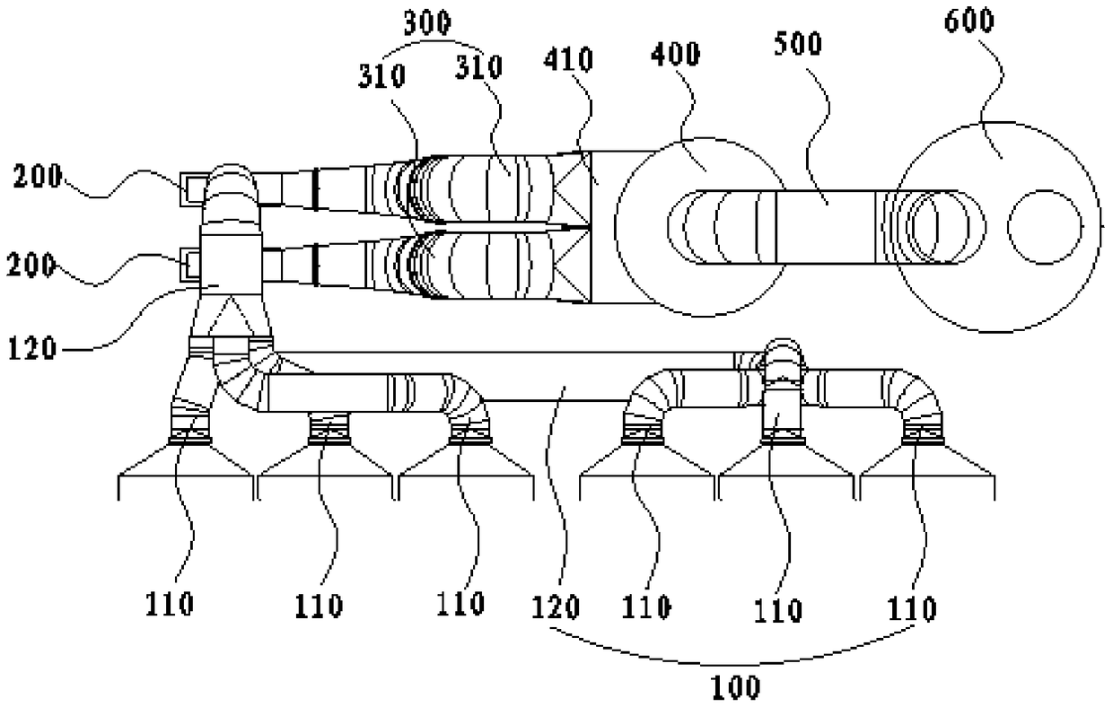
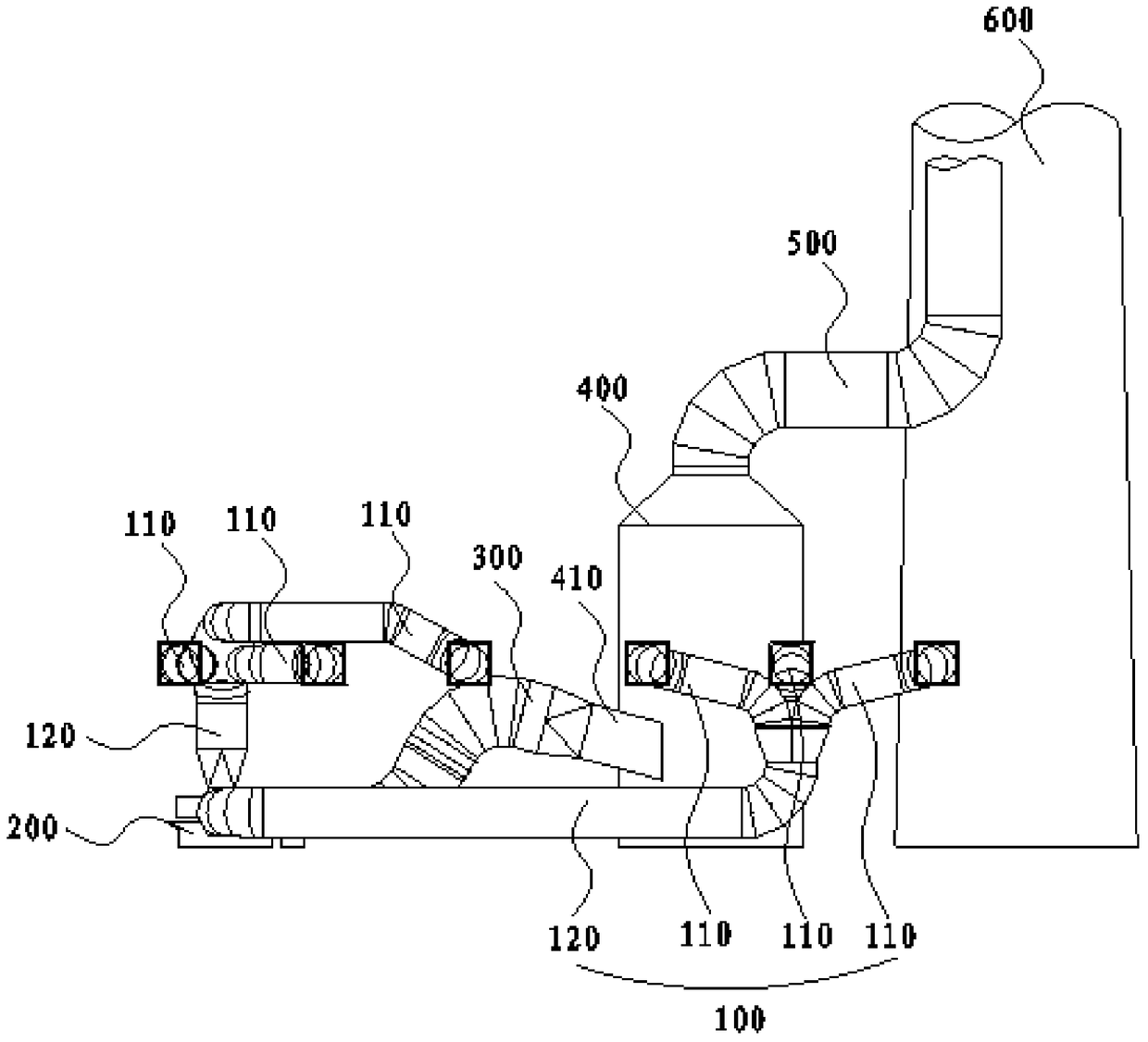
[0028] Such as figure 1 As shown, a joint layout structure of the flue gas system with six outlets of the dust collector and the flue gas system behind the double-row induced draft fan (that is, the arrangement structure of various equipment arranged behind the dust collector with six outlets), including the connection with the six outlets of the dust collector The double-row induced draft fan 200 (that is, two induced draft fans arranged horizontally and side by side), the desulfurization absorption tower 400 connected to the double-row induced draft fan 200, and the chimney 600 connected to the desulfurization absorption tower 400, and the double-row induced draft fans connected in sequence The center lines of the induced draft fan 200, the desulfurization absorption tower 400 and the chimney 600 are all located on the same plane. That is, the proje...


PUM


Abstract

The invention discloses a subsequent flue gas system combined arrangement structure for six outlets of a dust remover and induced draft fans in two rows. The structure comprises double rows of the induced draft fans connected with the six outlets of the dust remover, desulfurization absorption towers correspondingly connected with the double rows of induced draft fans, and chimneys connected with the desulfurization absorption towers, wherein the center lines of the double rows of induced draft fans, the desulfurization absorption towers and the chimneys connected in sequence are located on the same plane; the desulfurization absorption towers and the chimneys are vertically arranged side by side closely; the double rows of induced draft fans are transversely arranged at the outer sides of the desulfurization absorption towers side by side; the desulfurization absorption towers are arranged between the double rows of induced draft fans and the chimneys; and outlets of the double rows of induced draft fans are all aligned to the desulfurization absorption towers. All pieces of equipment behind the dust remover are arranged in a linear space in a combined manner, so that the equipment arrangement is more compact, the floor occupancy is reduced, and the flue connecting length is shortened.

Description

technical field [0001] The invention relates to the technical field of structural layout of a thermal power plant, in particular to a joint layout structure of a dust collector with six outlets and a flue gas system behind a double-row induced draft fan. Background technique [0002] In a coal-fired thermal power plant project, the distance from the outlet of the dust collector to the center line of the chimney is one of the important land occupation indicators. Most of the equipment in the flue gas system is arranged behind the boiler, and the layout of the front flue and the dust collector is relatively fixed. The size of the equipment layout behind the dust collector and the flue cost account for a large proportion of the initial investment of the power plant, and the resistance of the flue also directly affects the operating economy of the power plant. [0003] The main layout pattern of the equipment after the dust collector at home and abroad is basically to arrange th...

Claims


Application Information

Patent Timeline
Patent Type & Authority Patents(China)
IPC IPC(8): F23L17/00F23J15/02F23J11/00F23J13/00
CPCF23J11/00F23J13/00F23J15/02F23J2215/20F23L17/005
Inventor 杨劲范旭范永春李伟科马雪松
Owner CHINA ENERGY ENG GRP GUANGDONG ELECTRIC POWER DESIGN INST CO LTD
Why Eureka
Try Eureka