
Temperature and pressing measuring device on water-cooling wall surface of combustion chamber and machining method thereof

A technology of water-cooled wall surface and pressure measuring device, applied in the direction of measuring device, instrument, etc., can solve the problems of temperature value, pressure value, leakage of cooling medium, increase of flow resistance of cooling channel, etc., and achieve the effect of reducing flow resistance

Active Publication Date: 2016-03-16
NAT UNIV OF DEFENSE TECH
View PDF5 Cites 0 Cited by
  • Summary
  • Abstract
  • Description
  • Claims
  • Application Information

AI Technical Summary

Problems solved by technology

The existing temperature measurement and pressure measurement technology directly punches holes in the combustion chamber of the air heater. Since the combustion chamber is under high temperature and high pressure conditions for a long time, the cooling channel structure is used to cool the inner wall of the combustion chamber and directly punch holes on the inner wall of the combustion chamber, which will cause The flow resistance of the cooling channel increases, and the cooling effect of the measuring point hole is not good. The cooling medium is easy to leak from the measuring point hole to the combustion chamber, and the measured temperature and pressure values ​​are also affected.

Method used


Image

  • Temperature and pressing measuring device on water-cooling wall surface of combustion chamber and machining method thereof
  • Temperature and pressing measuring device on water-cooling wall surface of combustion chamber and machining method thereof

Examples


Embodiment 1

[0031] A method for processing a temperature and pressure measurement device on a water-cooled wall surface of a combustion chamber, comprising the following steps:

[0032] In the first step, the outer surface of the combustion inner wall 1 is finished, and the roughness of the outer surface of the combustion inner wall 1 is 6.3.

[0033] The second step is to process the water channel 9 on the outer surface of the combustion chamber wall 1 with a numerical control milling machine. The depth of the water channel 9 is 11 mm and the width is 4 mm; The two reinforcing ribs 11 process the effusion chamber 10, the effusion chamber 10 has a width of 20 mm and a length of 75 mm; and in the effusion chamber 10, a fish-eye type temperature measurement area 12, a fish-eye type pressure measurement area 13, and a fish-eye type pressure measurement area 13 are processed. Type temperature measuring area 12 is 15mm wide and 25mm long, and fisheye type pressure measuring area 13 is 11mm wid...

Embodiment 2

[0041] A method for processing a temperature and pressure measurement device on a water-cooled wall surface of a combustion chamber, comprising the following steps:

[0042] In the first step, the outer surface of the inner wall of the combustion chamber is finished, and the roughness of the outer surface of the inner wall of the combustion chamber is 3.2.

[0043]The second step is to process the water passage on the outer surface of the inner wall of the combustion chamber with a CNC milling machine. The depth of the water passage is 13mm and the width is 8mm; Outlet effusion cavity The effusion cavity is 40mm wide and 90mm long, and a fish-eye temperature measurement area and a fish-eye pressure measurement area are processed in the effusion cavity. The fish-eye temperature measurement area is 18mm wide and 30mm long, and the fish-eye type The pressure measuring area is 15mm wide and 25mm long.

[0044] The third step is to process two temperature measuring holes equal to ...


PUM

PropertyMeasurementUnit
lengthaaaaaaaaaa
widthaaaaaaaaaa
lengthaaaaaaaaaa

Abstract

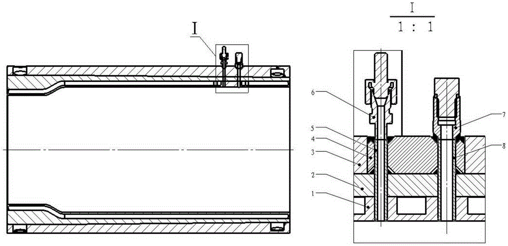
The invention discloses a temperature and pressing measuring device on a water-cooling wall surface of a combustion chamber and a machining method thereof. The device comprises a pressure-measuring pipe, a temperature-measuring pipe, a temperature-measuring joint nozzle, and a pressure-measuring joint nozzle, the temperature-measuring joint nozzle and the temperature-measuring pipe are integrally welded, the pressure-measuring joint nozzle and the pressure-measuring pipe are integrally welded, the temperature-measuring pipe and the pressure-measuring pipe are welded with a combustion chamber inner wall, a combustion chamber interlayer, and a block together, and the block and a cavity arranged on a combustion chamber jacket are welded together. The machining method includes: finishing of the external surface of the combustion chamber inner wall is performed; temperature-measuring holes and pressure-measuring holes are machined on the combustion chamber inner wall, the combustion chamber interlayer, and the block; the temperature-measuring pipe and the pressure-measuring pipe are welded with the combustion chamber inner wall and the combustion chamber interlayer together; the temperature-measuring pipe and the pressure-measuring pipe penetrate through the temperature-measuring hole and the pressure-measuring hole on the block and are welded with the block together, and the block is welded with the cavity on the combustion chamber jacket together. According to the device and the machining method thereof, the cooling effect of a measuring point area and the structural intensity of the combustion chamber are not affected, and the leakage of cooling media to the inner side of the combustion chamber and the outside of the combustion chamber interlayer is avoided.

Description

technical field [0001] The invention relates to the field of aerospace active ejection high-altitude simulation test systems, in particular to a temperature and pressure measurement device for a cooling combustion chamber and a processing method thereof. Background technique [0002] Air heater is one of the important ground equipment of supersonic vehicle or hypersonic vehicle, which is mainly used to simulate more extreme high-altitude physical environment. The working principle of the air heater is to burn oxygen, alcohol and mixed air to generate high-temperature and high-pressure gas in the combustion chamber. After passing through the throat, the high-temperature gas reaches the designed Mach number (the Mach number range is generally Ma3.5~7). Spray through nozzle. The combustion chamber is one of the key components of the air heater. The structure of the combustion chamber is generally divided into three layers, namely the inner wall, the reinforced interlayer, and...

Claims


Application Information

Patent Timeline
Patent Type & Authority Applications(China)
IPC IPC(8): G01D21/02B23P15/00
Inventor 李清廉王昌国戴训成肖礼王本寰
Owner NAT UNIV OF DEFENSE TECH
Learn More