
Liquid Distillation Condenser

A technology of distillation and condensation device and liquid, which is applied in distillation separation, heating water/sewage treatment, chemical instruments and methods, etc., can solve the problems of high use cost, heavy quality, low space utilization, etc., to improve efficiency and benefit, The effect of reducing production costs and accelerating evaporation

Active Publication Date: 2017-08-04
JINAN SENTE ELECTRONICS TECH
View PDF5 Cites 0 Cited by
  • Summary
  • Abstract
  • Description
  • Claims
  • Application Information

AI Technical Summary

Problems solved by technology

[0002] In the distilled water preparation device in the prior art, the condensing structure is installed on the upper part of the distillation bottle, fixed and supported on the lower distillation equipment installation platform through a special support frame, and the condensing pipe of the condensing structure is installed in a sealed cooling space. The cooling space is filled with cooling medium, and the cooling medium circulates continuously through the power of the circulating pump to circulate and cool the high-temperature water vapor in the condensation pipe to achieve the purpose of condensation. The existing problem is that a circulating cooling structure needs to be configured and the use cost is high. In addition, this The disadvantages of the condensing structure of this structure are heavy mass, high center of gravity, large shape, and poor overall stability. Because it is located on the upper part of the distillation equipment installation platform, it is easy to be bumped and scratched. At the same time, hot gas and liquid are unsafe. Interference and conflicts in the safe operation of operators
At the same time, since the top of the distillation bottle is connected to the bottom of the condensing structure, and the condensing structure is fixedly supported on the installation platform of the distillation equipment, the distillation bottle is inconvenient to remove, and it is easy to be bumped and scratched when it is removed. Generally, professional operators are required to install, disassemble, and store and transportation are inconvenient
In addition, the condensing structure, especially the inside of the condensing pipe, is not easy to clean after long-term use, and the high-temperature and high-pressure structure has poor safety protection, which is prone to safety hazards. In addition, due to the complex structure of the whole machine, it occupies a relatively large space and the space utilization rate is low.

Method used


Image

  • Liquid Distillation Condenser
  • Liquid Distillation Condenser
  • Liquid Distillation Condenser

Examples


Embodiment 1

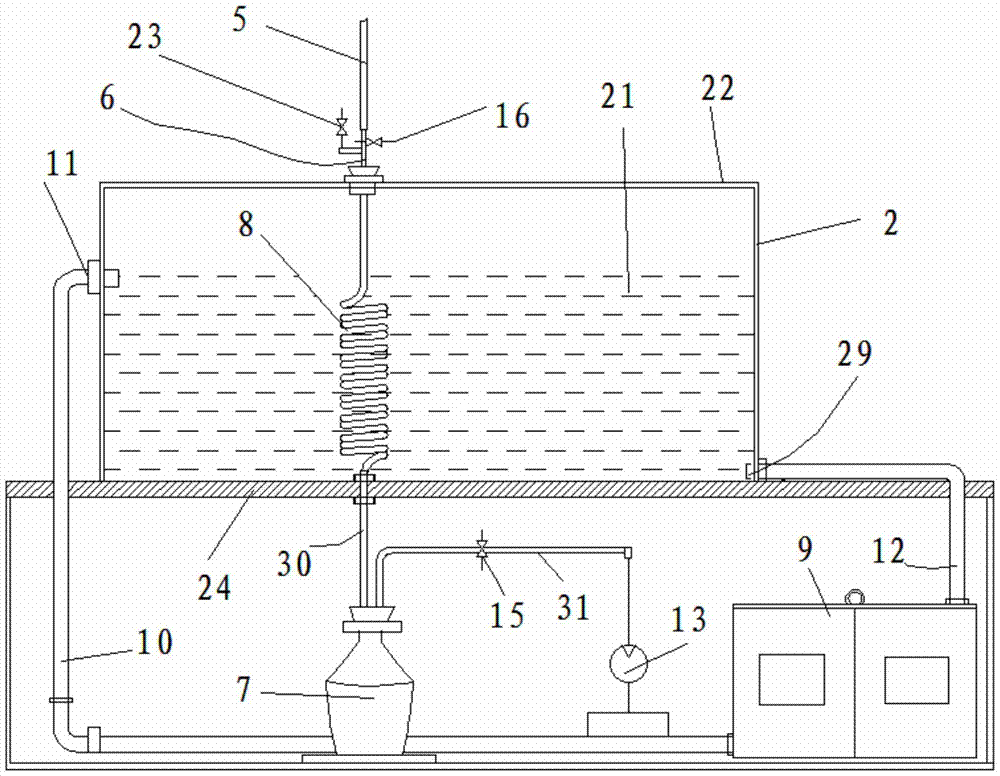
[0021] Example 1, such as figure 1 As shown, a liquid distillation condensing device includes a spiral condensation tube 8 and a condensation medium 21. The condensation medium 21 is arranged in a closed box 22, and the condensation tube 8 is arranged in the box 22 and connected with the box. The upper end of the condensation pipe 8 is connected with the two ends of the three-way valve 6 through the lower end of the conduit 5, the upper end of the conduit 5 is connected with the gas outlet of the retort, and the position of the box in the height direction is lower than the bottom of the retort, wherein The upper end of the spiral condensing pipe 8 is connected to the lower outlet of the three-way valve 6, the lower end of the conduit 5 is connected to the upper outlet of the three-way valve 6, the inlet of the three-way valve 6 is connected to the cleaning water pipeline, and a switch valve is arranged on the cleaning water pipeline. 23. An on-off valve 2 16 is provided on the...

Embodiment 2

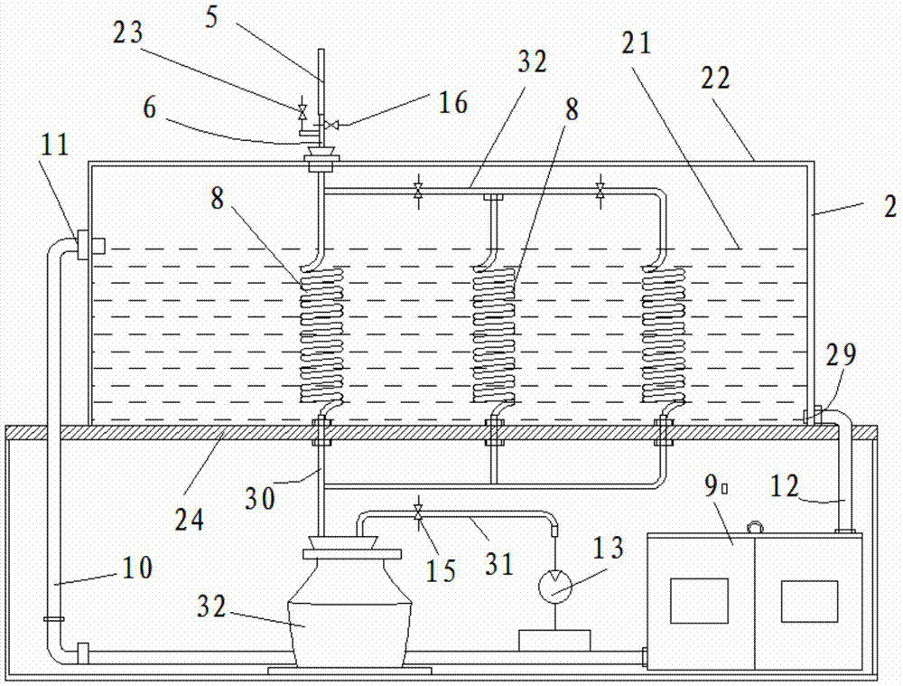
[0026] Such as figure 2 As shown, on the basis of Embodiment 1, a plurality of parallel condensing pipes 8 are provided in the casing 22 through pipeline connections, and a plurality of parallel condensing pipes 8 are connected with a large reflux bottle 32 at the bottom simultaneously, or respectively Connect with respective reflux bottle 7. When utilizing the technical scheme of this embodiment, the matching distilling bottle, heater, conduit 5, etc. adopt a structure larger than the size parameter of the single condensation tube 8 structure, and when the overall structure size increases less, It can greatly improve the working efficiency of distillation, especially suitable for occasions where a large amount of distilled water needs to be supplied, and where a single operator needs to operate multiple devices at the same time, reducing the labor intensity of a single operator and reducing labor costs. At the same time, the structure is compact, In the relatively tight use...

Embodiment 3

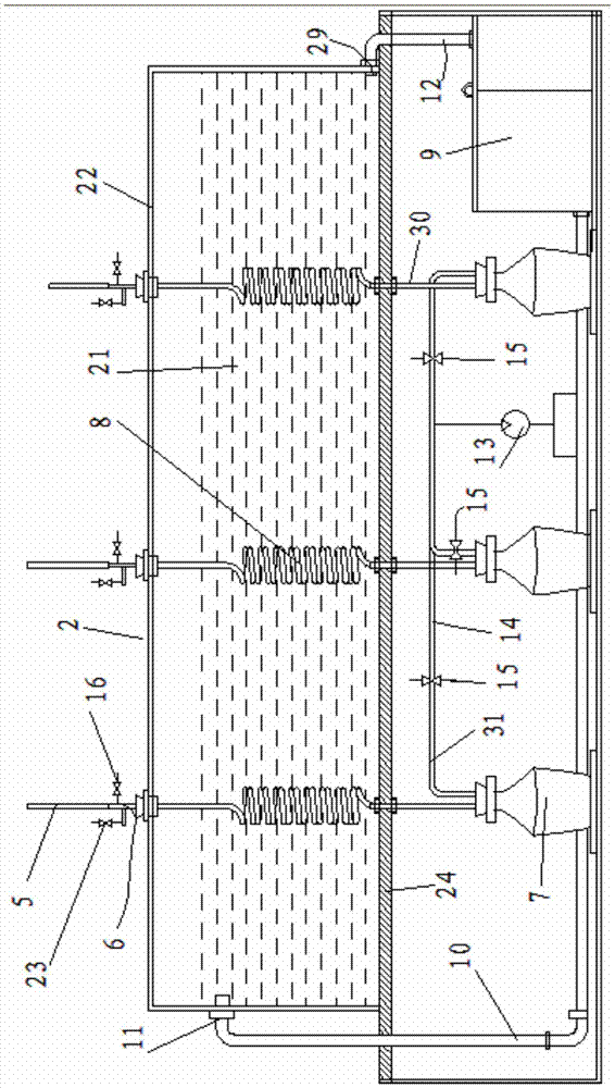
[0028] Such as image 3As shown, on the basis of Embodiment 1, the technical solution of this embodiment adopts multiple parallel conduits 5, the condensation pipe 8, the guide pipe 30 and the conduits 5 are arranged correspondingly, and each conduit 5 is connected with the corresponding parallel collectors respectively. The retort, the heater are connected, and the reflux bottle 7 corresponds to the guide tube 30, and the retort, the heater, the conduit 5, etc. in this embodiment can adopt a structure smaller than the size parameter of the single condensation pipe 8 structure, Due to the small size of each set of distillation structures, enough individual distillation bottles, heaters and other distillation structures can be arranged on a support platform 20 at the same time, and even the same distillation structure can be arranged around a large support platform 20 , this kind of technical scheme is suitable for public places such as schools, for students to conduct distilla...


PUM


Abstract

The invention discloses a liquid distillation condensation device, comprising a condensation pipe and a condensation medium, wherein the condensation medium is arranged in a box, the condensation pipe is arranged inside the box, the spiral condensation pipe is connected with a guide pipe, the upper end of the guide pipe is connected with a distillation bottle, the box is lower than the bottom of the distillation bottle, the spiral condensation pipe is connected with a backflow bottle, the backflow bottle is arranged at the lower part of a shell, a box wall at one side of the box is provided with a condensation medium inlet, the upper part of a box wall at another side of the box is provided with a condensation medium outlet, the condensation medium inlet is connected with an outlet of a refrigerating unit, the condensation medium outlet is connected with an inlet of the refrigerating unit, a bottleneck of the backflow bottle is provided with an air outlet pipeline, and the air outlet pipeline is connected with a negative pressure pump, and is provided with a switching valve III. The liquid distillation condensation device is compact in structure and low in gravity center, certain negative pressure in the distillation bottle can be kept, the evaporating temperature of distilled water is lowered, the evaporation rate of the distilled water is quickened, distilled water is obtained as much as possible in the same evaporation time, power consumption is lowered, use and production costs are lowered, and efficiency and benefits are improved.

Description

technical field [0001] The invention relates to the technical field of distillation equipment, in particular to a liquid distillation condensing device. Background technique [0002] In the distilled water preparation device in the prior art, the condensing structure is installed on the upper part of the distillation bottle, fixed and supported on the lower distillation equipment installation platform through a special support frame, and the condensing pipe of the condensing structure is installed in a sealed cooling space. The cooling space is filled with cooling medium, and the cooling medium circulates continuously through the power of the circulating pump to circulate and cool the high-temperature water vapor in the condensation pipe to achieve the purpose of condensation. The existing problem is that a circulating cooling structure needs to be configured and the use cost is high. In addition, this The disadvantages of the condensing structure of this structure are heavy...

Claims


Application Information

Patent Timeline
Patent Type & Authority Patents(China)
IPC IPC(8): B01D3/00C02F1/04
CPCB01D3/00C02F1/04
Inventor 段作敏孙树旺杨连宽
Owner JINAN SENTE ELECTRONICS TECH
Learn More