Template laser cutting equipment provided with template fixture

A technology of laser template and cutting equipment, used in laser welding equipment, welding/cutting auxiliary equipment, welding equipment, etc., can solve the problems of heavy equipment, inability to complete, large size, etc., to achieve short operation time, maintain stability, production Efficient effect

Inactive Publication Date: 2016-03-23
DONGGUAN QINZHI IND DESIGN CO LTD
View PDF5 Cites 9 Cited by
  • Summary
  • Abstract
  • Description
  • Claims
  • Application Information

AI Technical Summary

Problems solved by technology

Since the laser head is fixed and the template is moved, the required platform is large and the equipment is he

Method used


Image

  • Template laser cutting equipment provided with template fixture
  • Template laser cutting equipment provided with template fixture
  • Template laser cutting equipment provided with template fixture

Examples


Example Embodiment

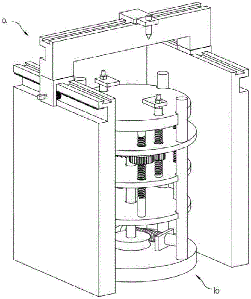
[0037] like figure 1 What is claimed is a laser template cutting device provided with a template clamp, comprising a cutting mechanism a and a template clamp b.

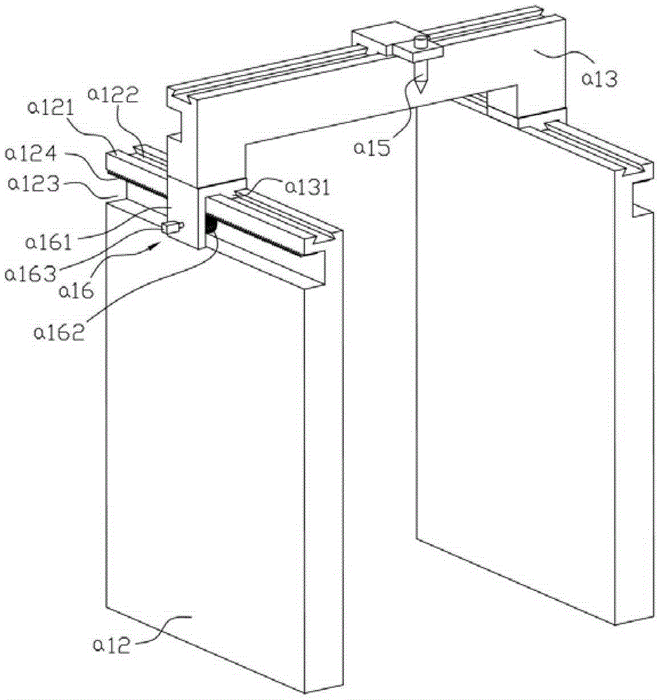
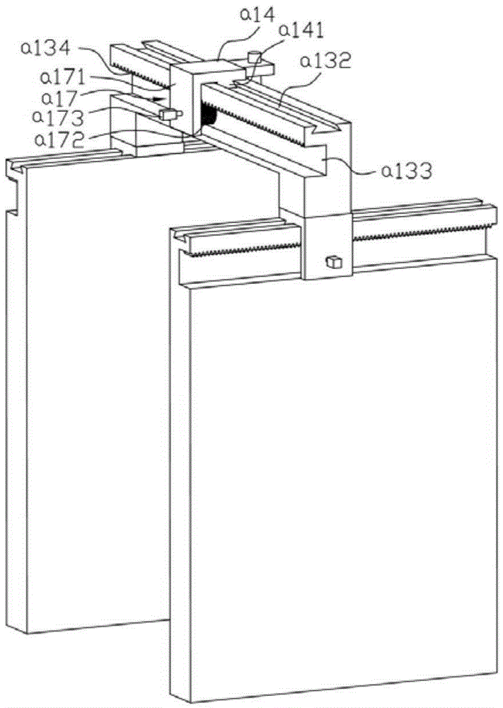
[0038] to combine figure 2 , image 3 , the cutting mechanism a includes a pair of left and right frame plates a12, a beam a13 across the pair of frame plates, a laser frame a14 installed on the beam, and a laser head a15 installed on the laser frame; the pair A Y-direction slideway is provided on the frame plate, and an X-direction slideway is provided on the beam. On the X-direction slideway of the beam; the laser head is connected with the laser generator through the reflection device.

[0039] In the above-mentioned cutting mechanism a, the pair of frame plates a12 includes a left frame plate and a right frame plate, a first Y-direction slideway a121 is provided on the left frame plate, and a first Y-direction slideway a121 is provided on the right frame plate. Two Y-direction slideways; the first Y-directio...


PUM


Abstract

The invention discloses template laser cutting equipment provided with a template fixture. The template laser cutting equipment comprises a cutting mechanism and the template fixture, wherein the cutting mechanism comprises a laser head; the laser head makes two-dimensional movement through an X-direction slideway and Y-direction slideways; and the template fixture is positioned between two rack plates of the cutting mechanism and is positioned below the laser head; a worm gear in the template fixture, through driving a threaded rod, drives a first chassis to descend with a locking block, and drives a second chassis to rise with a fixed disk. In this way, a workpiece on the fixed disk is clamped up and down by the fixed disk and the locking block, and the cutting of a template is completed by a laser beam. The template laser cutting equipment is high in speed and efficiency, and cuts smoothly, easily and neatly.

Description

Technical field: [0001] The invention relates to the technical field of laser templates, in particular to a laser template cutting device provided with a template clamp. Background technique: [0002] Stencils, especially large stencils, are widely used in a wide range of applications. Electricity, heat, or knife cutting are generally used for cutting. With the wide application of lasers, laser cutting is gradually being used in the field of stencil cutting due to its high speed and high efficiency. The principle is that under the action of a high-voltage electric field, the electrons in the discharge tube move and collide with the gas to generate photoelectrons, which are accelerated through a long distance to form a laser beam with a wavelength of 10.64um to be emitted to cut the template. The laser cutting machine currently used is mainly composed of a mobile platform and a laser head. The template is placed on the mobile platform, and the laser head completes the cutting...

Claims


Application Information

Patent Timeline
IPC IPC(8): B23K26/08B23K26/38B23K37/04B23K101/18
CPCB23K26/0876B23K26/0823B23K26/38B23K37/0408B23K2101/18
Inventor 高扬
Owner DONGGUAN QINZHI IND DESIGN CO LTD
Why Eureka
Try Eureka