
Digital hydraulic flow regulation system

A technology of flow regulation and digital hydraulics, which is applied in the direction of fluid pressure actuators, servo motors, servo motor components, etc., can solve the problems of small flow and low pressure, and achieve the effect of increasing the degree of freedom

Inactive Publication Date: 2016-03-23
ZHEJIANG UNIV
View PDF6 Cites 11 Cited by
  • Summary
  • Abstract
  • Description
  • Claims
  • Application Information

AI Technical Summary

Problems solved by technology

[0003] However, due to the inter-restrictive relationship between the quality of the spool, hydraulic power and frequency response, simple high-speed on-off valves are faced with the limitations of low pressure and small flow, and their application in construction machinery has certain limitations.

Method used


Image

  • Digital hydraulic flow regulation system
  • Digital hydraulic flow regulation system

Examples


Embodiment Construction

[0017] The present invention will be further described below in conjunction with the accompanying drawings and specific examples.

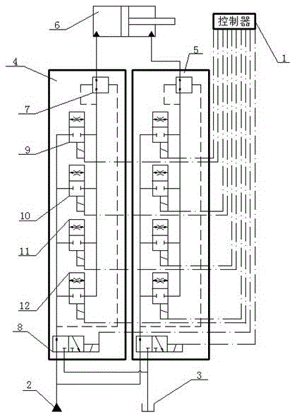
[0018] like figure 1 As shown, the present invention includes a controller 1, a power oil source 2, an oil return tank 3, a first digital control unit 4, a second digital control unit 5 and a hydraulic cylinder 6; The oil inlet of the oil inlet and outlet selector valve 8 is connected with the oil inlet of the oil inlet and outlet selector valve 8 in the second digital control unit 5; the oil inlet and outlet selector valve 8 in the first digital control unit 4 The oil return port of the second digital control unit 5 and the oil return port of the oil inlet and return reversing valve 8 in the second digital control unit 5 are connected with the oil return tank 3; the rodless cavity of the hydraulic cylinder 6 is connected with the pressure compensator in the first digital control unit 4 7 is connected to the working oil port, and the rod cavity o...


PUM


Abstract

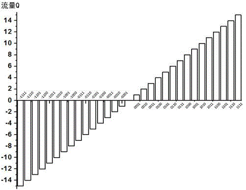
The invention discloses a digital hydraulic flow regulation system. A power oil source is connected with the oil inlet of an inlet and return oil reversing valve in a first digital control unit and the oil inlet of an inlet and return oil reversing valve in a second digital control unit. The return opening of the inlet and return oil reversing valve in the first digital control unit and the return opening of the inlet and return oil reversing valve in the second digital control unit are connected with an oil return tank. A rodless cavity of a hydraulic cylinder is connected with the working port of a pressure compensator in the first digital control unit. A rod cavity of the hydraulic cylinder is connected with the working port of a pressure compensator in the second digital control unit. A controller is electrically connected with the two digital control units. High-speed switching valves use PWM digital signals to control. An amplifier board and a digital-to-analogue conversion device are arranged between the controller and the high-speed switching valve. Orifice areas of the four high-speed switching valves are in two-time relations. Through combinational coding and inlet and return oil switching, a single digital control unit can realize adjustable flow of -15Q-15Q.

Description

technical field [0001] The invention relates to an electro-hydraulic control system, in particular to a digital hydraulic flow regulating system. Background technique [0002] The earliest research on high-speed switching valves began in the late 1950s. After the 1970s, with the development and application of computer technology, electro-hydraulic digital control technology has become an important means to realize mechatronics, and it is an ideal method to realize high-speed and high-precision control of hydraulic systems. The high-speed switching valve can adjust the switching time and frequency of the valve port through the duty ratio of the PMW digital signal. Compared with high-speed switching valves, traditional switching valves have longer switching time and lower switching frequency, which cannot meet the requirements of high-precision electro-hydraulic control systems. Although the electro-hydraulic servo valve can obtain high working precision, its anti-pollution ...

Claims


Application Information

Patent Timeline
Patent Type & Authority Applications(China)
IPC IPC(8): F15B11/00F15B13/02
CPCF15B11/00F15B13/02
Inventor 张斌王双杨华勇
Owner ZHEJIANG UNIV
Learn More