A device for real-time testing of nonlinear parameters of cmos image sensors
What is AI technical title?
AI technical title is built by Patsnap AI team. It summarizes the technical point description of the patent document.
An image sensor and real-time testing technology, which is applied in testing optical performance and other directions, can solve the problem of low test accuracy and achieve the effect of ensuring reliability and safety
Active Publication Date: 2018-01-30
HARBIN INST OF TECH
View PDF4 Cites 0 Cited by
Summary
Abstract
Description
Claims
Application Information
AI Technical Summary
This helps you quickly interpret patents by identifying the three key elements:
Problems solved by technology
Method used
Benefits of technology
Problems solved by technology
[0005] The present invention aims to solve the problem that the existing manual testing method for nonlinear parameters of CMOS image sensors leads to low test accuracy. The present invention provides a device for real-time testing of nonlinear parameters of CMOS image sensors
Method used
Image
Click on the blue label to locate the original text in one second.
Reading with bidirectional positioning of images and text.
Examples
specific Embodiment approach 1
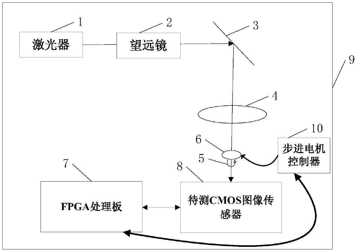
[0019] Specific implementation mode one: see figure 1 Describe this embodiment, a device for real-time testing of nonlinear parameters of a CMOS image sensor described in this embodiment, which includes a laser 1, a telescope 2, a mirror 3, a focusing lens 4, a rotating mechanism 5, and an aperture 6. FPGA processing board 7, dark box 9 and steppermotor controller 10;
[0020] Laser 1, telescope 2, mirror 3, focusing lens 4, rotating mechanism 5, diaphragm 6, FPGA processing board 7 and steppermotor controller 10 are all arranged in the dark box 9;
[0021] The FPGA processing board 7 collects and controls the position information of the rotating mechanism 5 through the stepping motor controller 10, so that the rotating mechanism 5 drives the diaphragm 6 to move, and the diaphragm 6 is rotated and translated by 360°, so that the light spot is placed on the CMOS to be tested. movement of the photosensitive surface of the image sensor 8,
[0031] Specific implementation mode two: see figure 1 This embodiment is described. The difference between this embodiment and the device for real-time testing of nonlinear parameters of a CMOS image sensor described in Embodiment 1 is that the length, width and height of the dark box are 0.7m respectively , 0.7m and 0.5m.
[0032] In this embodiment, the test is carried out in a dark box, mainly to prevent the interference of background light, so that the pros and cons of the nonlinear parameters of the CMOS image sensor chip can be evaluated more objectively.
specific Embodiment approach 3
[0033] Specific implementation mode three: see figure 1 This embodiment is described. The difference between this embodiment and the device for real-time testing of nonlinear parameters of a CMOS image sensor described in the first embodiment is that the size of the spot image is 100×100 pixels.
PUM
Abstract
A device for nonlinear parameter real-time testing of a CMOSimage sensor belongs to the field of CMOSimage sensor testing and solves the problem that an existing method for manual testing of a nonlinear parameter of the CMOSimage sensor leads to low testing accuracy. An FPGA processing plate collects position information of a rotation mechanism and controls the rotation mechanism by a stepping motor controller; laser emitted by a laser device is collimated by a telescope, enters a reflecting mirror, is then reflected by the reflecting mirror and focused by a focus lens and finally enters the to-be-tested CMOS image sensor by a diaphragm; the to-be-tested CMOS image sensor sends a collected light spot image to the FPGA processing plate via a parallel bus; and the FPGA processing plate processes the collected light spot image in real time to obtain an NU value, and the NU value is compared with a set threshold value, so that whether the to-be-tested CMOS image sensor is qualified is determined. The device is used to detect the image sensor.
Description
technical field [0001] The invention belongs to the field of CMOS image sensor testing. Background technique [0002] In satelliteoptical communication, CMOS image sensor is the main component of the optical system. In order to realize the reliability and safety of its space application, it is very important for the screening test of CMOS image sensor chips, especially the testing and screening of its nonlinear parameters, which will directly affect the output image of CMOS image sensor chips The amplitude and quality of the signal will affect the acquisition and tracking accuracy of the satelliteoptical communicationsystem to a certain extent. [0003] The method usually used is manual testing to test the nonlinearity of the CMOS image sensor chip. The disadvantage is that the test accuracy of the manual method is difficult to guarantee, and it is also difficult to guarantee a comprehensive test of the full field of view of the CMOS image sensor chip. . Therefore, the...
Claims
Application Information
Patent Timeline
Application Date:The date an application was filed.
Publication Date:The date a patent or application was officially published.
First Publication Date:The earliest publication date of a patent with the same application number.
Issue Date:Publication date of the patent grant document.
PCT Entry Date:The Entry date of PCT National Phase.
Estimated Expiry Date:The statutory expiry date of a patent right according to the Patent Law, and it is the longest term of protection that the patent right can achieve without the termination of the patent right due to other reasons(Term extension factor has been taken into account ).
Invalid Date:Actual expiry date is based on effective date or publication date of legal transaction data of invalid patent.

