Preparation method for photonic crystal plastic scintillator

A plastic scintillator and photonic crystal technology, which is applied in the field of nuclear radiation measurement, can solve the problems of easily damaged plastic scintillator, complexity, scintillator tearing, etc., and achieve the effects of avoiding luminous interference, simplifying the preparation process, and easy operation

Inactive Publication Date: 2016-03-23
TONGJI UNIV
View PDF8 Cites 11 Cited by
  • Summary
  • Abstract
  • Description
  • Claims
  • Application Information

AI Technical Summary

Problems solved by technology

However, the process of preparing photonic crystals by traditional nanoimprint technology includes the process of photoresist spin-coating and pattern transfer. This process is relatively complicated, and it faces serious challenges for plastic scintillators. The chemical reaction of the scintillator destroys the scintillator. Secondly, the ion beam etching and other processes used in the process of pattern transfer can easily destroy the plastic scintillator itself, resulting in a sharp drop in its luminous performance. Again, for some plastic scintillators with a thickness less than 1mm, The image transfer process is very easy to damage the scintillator, resulting in tearing or deformation of the scintillator

Method used


Image

  • Preparation method for photonic crystal plastic scintillator
  • Preparation method for photonic crystal plastic scintillator

Examples


Embodiment 1

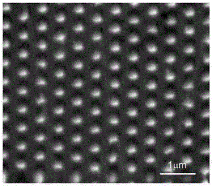
[0025] Photonic crystals were prepared on the surface of the plastic scintillator model NE102. The selected template structure was a columnar periodic array with a triangular structure, the period was 600nm, the diameter of the columns was 300nm, the height was 300nm, and the template area was 20×20mm 2 , the template material is quartz, and the structure of the obtained photonic crystal is the complementary structure of the template pattern, that is, a periodic array of holes in a triangular structure. The period is 600nm, the diameter of the holes is 300nm, and the height is 300nm. 20mm 2 .

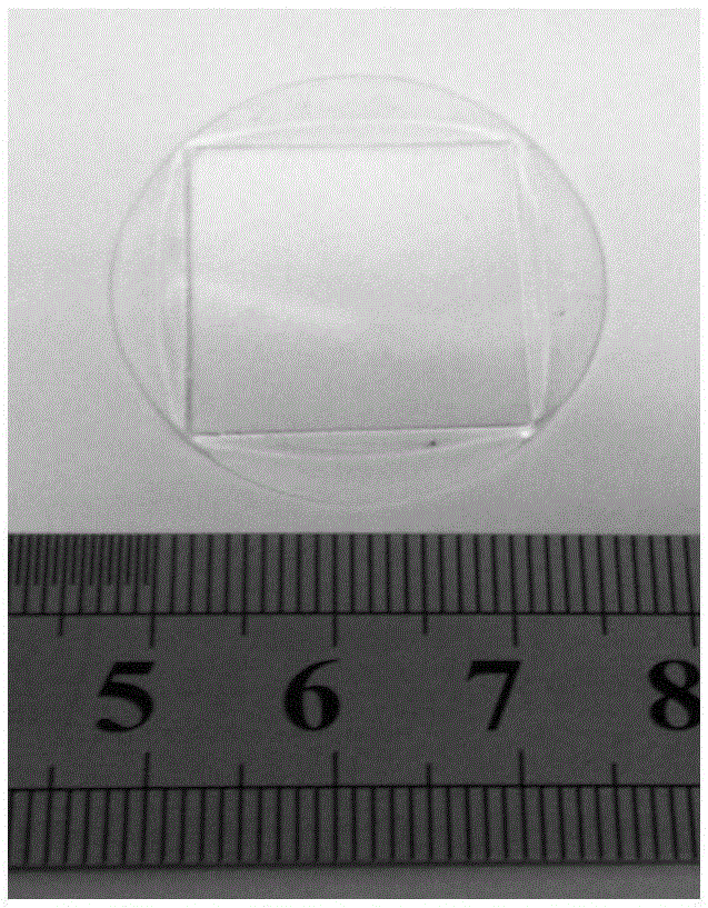
[0026] The preparation process is as follows: Step 1: purchase NE102 plastic scintillator, cut and polish to obtain a scintillator with a flat surface, and its size is 3 cm in diameter and 0.5 mm in thickness. Purchase a template piece of the above structure. Step 2: Perform anti-sticking treatment on the template, put the template in a nitrogen-protected flask, and slowly pour in per...

Embodiment 2

[0028] Photonic crystals were prepared on the surface of EJ212 plastic scintillator. The selected template structure was a square columnar periodic array with a period of 500nm, a column diameter of 250nm, a height of 300nm, and a template area of ​​8.5×8.5mm. 2 , the template material is silicon, and the structure of the obtained photonic crystal is the complementary structure of the template pattern, that is, a periodic array of holes with a square structure, the period is 500nm, the diameter of the holes is 250nm, and the height is 300nm. The total area obtained is 8.5× 8.5mm 2 .

[0029] The preparation process is as follows: Step 1: EJ212 plastic scintillator was purchased, cut and polished to obtain a scintillator with a flat surface, and its size was 2 cm in diameter and 1 mm in thickness. Purchase a template piece of the above structure. Step 2: Anti-adhesive treatment of the template, put the template in a nitrogen-protected flask, and slowly pour in perfluoroquinyl...


PUM


Abstract

The invention relates to a preparation method for a photonic crystal plastic scintillator. A proper stamping template and needed plastic scintillators are selected; antistick processing is carried out on the template; thermal nanometer stamping is carried out on the plastic scintillators by utilizing the template after antistick processing; and the template is separated from the plastic scintillators after stamping to obtain the photonic crystal structure complementary with the template in figure. Compared with the prior art, figure transfer is not needed, the complex process of spin coating of photoresist and subsequent figure transfer as in most photonic crystal preparation process are avoided, and the whole preparation process is greatly simplified.

Description

technical field [0001] The invention belongs to the field of nuclear radiation measurement, in particular to a method for preparing a photonic crystal plastic scintillator. Background technique [0002] Plastic scintillator is an important member of the scintillator family, and has important applications in nuclear radiation measurement, especially neutron measurement, neutron gamma screening measurement and beta ray measurement. The refractive index of plastic scintillators is usually between 1.4 and 1.6. When scintillation light enters the air, it will encounter total reflection at the interface, thus limiting the effective output of light. An improved method to increase light output is to prepare photonic crystal structures on the surface of plastic scintillators, and use the coupling effect of total internal reflection light and photonic crystal structures to generate effective extraction modes, thereby increasing light output and improving the sensitivity of the detecti...

Claims


Application Information

Patent Timeline
Patent Type & Authority Applications(China)
IPC IPC(8): G01T1/00G01T3/06B82Y40/00
CPCB82Y40/00G01T1/003G01T3/06
Inventor 刘波刘金良陈亮程传伟陈鸿顾牡欧阳晓平
Owner TONGJI UNIV
Why Eureka
Try Eureka