External optical path compensation adjusting device and laser device formed thereby

A technology of compensation adjustment and external optical path, which is applied in the laser field, can solve the problems of difficult heating control, affecting the effect of compensation adjustment, and deterioration of beam directivity, so as to avoid beam directivity problems, improve overall stability, and output power stable effect

Inactive Publication Date: 2016-03-23
HUAZHONG UNIV OF SCI & TECH
View PDF9 Cites 11 Cited by
  • Summary
  • Abstract
  • Description
  • Claims
  • Application Information

AI Technical Summary

Problems solved by technology

Disadvantages of this compensation adjustment method: First: the reaction time of heating is long, and the advantages of real-time adjustment are not obvious; second: heating control is difficult, which will affect the effect of compensation adjustment
This method has strong real-time performance, but the adjustment accuracy is not high. In order to obtain high-precision adjustment, it is necessary to redesign and select a new micro-displacement positioner and redesign the adjustment system.
In addition, this method does not make any corrections to the offset optical axis, and only adjusts the position of the spatial filter aperture to adapt to the misalignment of the optical path, the beam directivity will become poor, and the practicability is not strong

Method used


Image

  • External optical path compensation adjusting device and laser device formed thereby
  • External optical path compensation adjusting device and laser device formed thereby
  • External optical path compensation adjusting device and laser device formed thereby

Examples


Embodiment Construction

[0031] In order to make the objectives, technical solutions and advantages of the present invention clearer, the following further describes the present invention in detail with reference to the accompanying drawings and embodiments. It should be understood that the specific embodiments described herein are only used to explain the present invention, but not to limit the present invention. In addition, the technical features involved in the various embodiments of the present invention described below can be combined with each other as long as they do not conflict with each other.

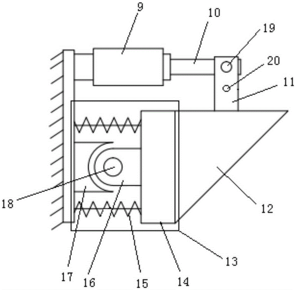
[0032] Such as figure 1 It is shown that the optical path compensation adjustment device of this embodiment is mainly composed of a turning mirror 12, a piezoelectric ceramic micro-displacement driver 9 and a rotatable base 13. The rotatable base 13 includes a metal block 14, a spring set 15, a concave round base 16 and a convex round handle 17 matched with it. One end of the convex round handle 17 is ...


PUM


Abstract

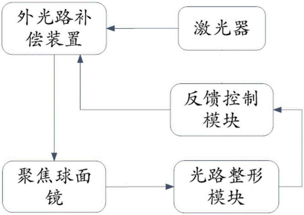
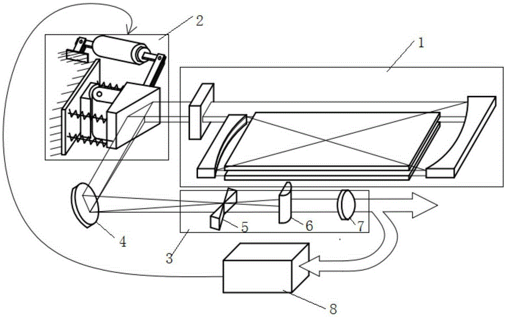
The invention provides a turning mirror adjustment-based external optical path compensation adjusting device, which comprises a turning mirror, a piezoelectric ceramic micro-displacement actuator and a rotatable base. The turning mirror is driven to rotate by changing the size of a voltage applied to the micro-displacement actuator, so that automatic compensation of an optical path is achieved. On this basis, the invention provides an external optical path compensation adjusting device-based laser device, which comprises a laser device body, the external optical path compensation adjusting device, an optical path shaping module, a focusing spherical mirror and a feedback control module, wherein the feedback control module detects an output laser and adjusts an offset light beam to a standard position by adjusting the deflection angle of the turning mirror through an optical path compensation adjusting system; the stability of laser output powers and the stability of the modes of the laser device under various duty ratios can be ensured; and the overall stability of the laser device is improved, so that efficient and stable working of a radio frequency slab laser device processing system is ensured; the processing quality of a processed device is ensured; and the processing efficiency is improved.

Description

Technical field [0001] The invention belongs to the field of laser technology, and designs and develops a high-power radio frequency slat CO 2 The laser’s turning mirror adjusts and reshapes the optical path offset compensation system. 2 The optical path deviation of the shaping system caused by the thermal distortion of the laser cavity mirror is compensated. Background technique [0002] High power slat CO 2 The laser beam quality is high, the structure is very compact and small, does not require a gas heat exchanger, the optical loss is low, the thermal stability is very high, the gas consumption is low, there is no gas flow, the cavity optics will not be polluted, and the beam quality factor M 2 Up to 1.2, representing the current CO 2 The development direction of lasers. The laser adopts an unstable-waveguide hybrid cavity design structure, and the resonant cavity is composed of an output mirror, a reflection mirror and a discharge slab waveguide. The near-field output spot ...

Claims


Application Information

Patent Timeline
Patent Type & Authority Applications(China)
IPC IPC(8): H01S3/02G02B7/00
CPCH01S3/02G02B7/00
Inventor 唐霞辉韩蒙蒙秦应雄夏燃肖龙胜高雪松万辰皓
Owner HUAZHONG UNIV OF SCI & TECH
Why Eureka
Try Eureka