Inverter circuit and driving method thereof

An inverter and circuit technology, applied in logic circuits, electrical components, pulse technology, etc., can solve the problems of slow response speed, high power consumption, low output swing, etc., achieve fast charging, reduce energy consumption, and promote discharge speed effect

Inactive Publication Date: 2016-03-23
SOUTH CHINA UNIV OF TECH
View PDF1 Cites 5 Cited by
  • Summary
  • Abstract
  • Description
  • Claims
  • Application Information

AI Technical Summary

Problems solved by technology

However, since only N-type oxide thin film transistors can work stably, the traditional inverter circuit structure applied to oxide thin film transistors will have the characteristics of high power consumption, low output swing, and slow response speed.

Method used


Image

  • Inverter circuit and driving method thereof
  • Inverter circuit and driving method thereof
  • Inverter circuit and driving method thereof

Examples


Embodiment

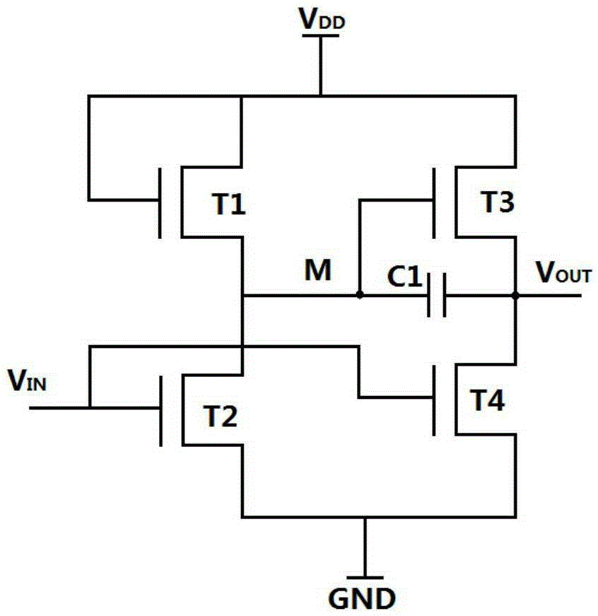
[0024] Such as figure 1 As shown, an inverter circuit is composed of first, second, third and fourth transistors and capacitors;

[0025] The gate and drain of the first transistor T1 are connected to the high voltage V DD connected, the source of the first transistor T1 is connected to the source of the second transistor T2, the gate of the third transistor T3, and one end of the capacitor C1;

[0026] The gate of the second transistor T2 and the gate of the fourth transistor T4 are respectively connected to the input signal V IN and connected, the drain of the second transistor T2 is connected to the low voltage GND;

[0027] The drain of the third transistor T3 is connected to the high voltage V DD The source of the third transistor T3, the source of the fourth transistor T4 and the other end of the capacitor C1 are respectively connected to the output port V OUT connected;

[0028] The drain of the fourth transistor T4 is connected to the low voltage GND.

[0029] Th...


PUM


Abstract

The invention discloses an inverter circuit and a driving method thereof. The inverter circuit is composed of first, second, third and fourth transistors and a capacitor. The grid electrode and drain electrode of the first transistor are in connection with high voltage; the source electrode of the first transistor is in connection with the source electrode of the second transistor, the gird electrode of the third transistor, and one end of the capacitor; the grid electrode of the second transistor, and the grid electrode of the fourth transistor are both in connection with an incoming signal; the drain electrode of the second transistor is in connection with low voltage; the drain electrode of the third transistor is in connection with the high voltage; the source electrode of the third transistor, the source electrode of the fourth transistor, and the other end of the capacitor are all in connection with an output port; the drain electrode of the fourth transistor is in connection with the low voltage. The inverter circuit can realize inverter low power consumption.

Description

technical field [0001] The invention relates to the field of thin film transistor integrated circuits, in particular to an inverter circuit and a driving method thereof. Background technique [0002] An inverter is the basic unit of a digital integrated circuit. When the input signal is high, the output signal is low; when the input signal is low, the output signal is high. A traditional CMOS inverter consists of a P-type transistor and an N-type transistor. With the development of thin film transistor technology, especially the development of oxide semiconductor thin film transistors, the use of unipolar transistors to directly integrate digital circuits is an important research direction for the development of scientific and industrial circles. [0003] Oxide semiconductor transistors have high carrier mobility, high compatibility with amorphous silicon technology, low manufacturing cost, good uniformity and high current switching ratio, etc., and have good development p...

Claims


Application Information

Patent Timeline
Patent Type & Authority Applications(China)
IPC IPC(8): H03K19/082
CPCH03K19/088
Inventor 吴为敬李冠明夏兴衡张立荣周雷徐苗王磊彭俊彪
Owner SOUTH CHINA UNIV OF TECH
Why Eureka
Try Eureka