Oil slick collection method

A technology for oil slicks and oil slicks on the water surface, which is applied in general water supply conservation, cleaning of open water surfaces, water conservancy projects, etc., can solve problems such as incomplete recovery, rising oil slick recovery costs, and difficult operation, so as to reduce recovery costs, The effect of reducing post-processing procedures and efficient collection

Inactive Publication Date: 2016-03-30
XINJIANG TECHN INST OF PHYSICS & CHEM CHINESE ACAD OF SCI +2
View PDF11 Cites 15 Cited by
  • Summary
  • Abstract
  • Description
  • Claims
  • Application Information

AI Technical Summary

Problems solved by technology

This kind of oil recovery ship has some improvements compared with the purely mechanical oil recovery ship, and can selectively recover oil slicks, but the recovery is not complete. In actual use, the oil recovery ship needs at least two ships to work together to complete the cleaning and recovery of the spilled oil, which is difficult to operate. Larger, which also makes the oil slick recovery cost significantly increased

Method used


Image

  • Oil slick collection method
  • Oil slick collection method
  • Oil slick collection method

Examples


Embodiment 1

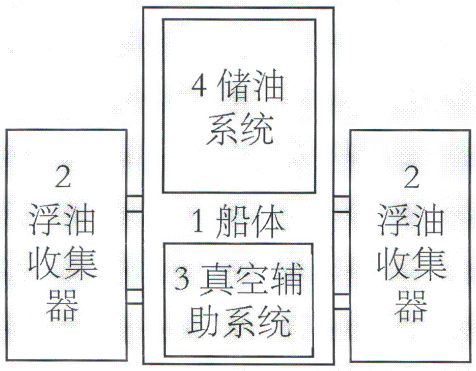
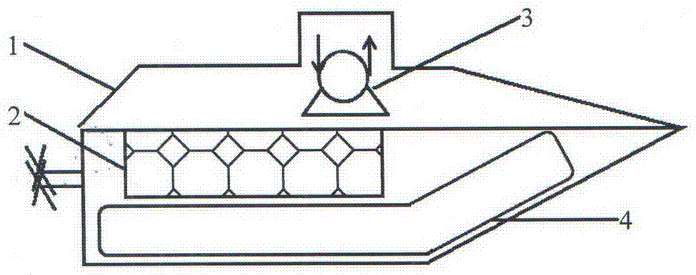
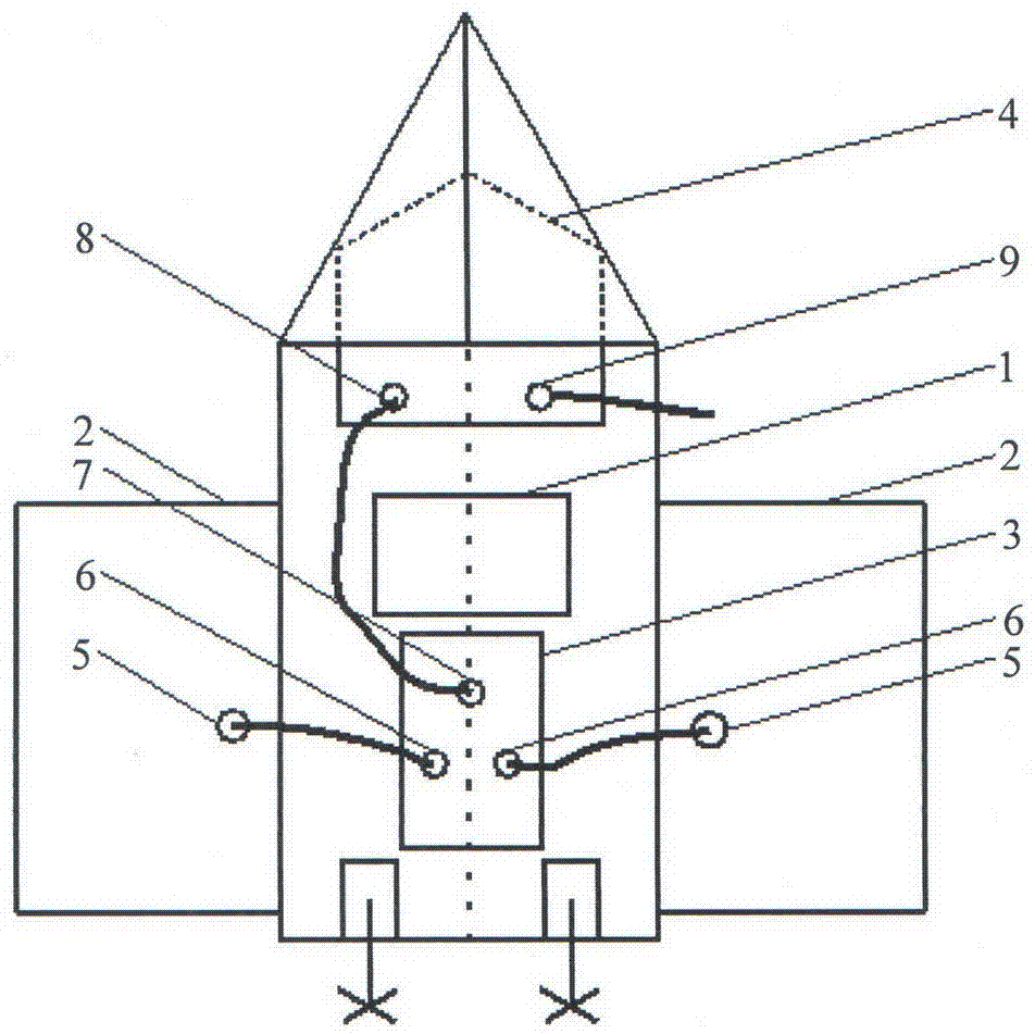
[0023] The surface oil slick collection device is composed of four parts: the hull, the oil slick collector, the vacuum auxiliary system and the oil storage system; the oil slick collector 2 is fixed on both sides of the hull 1, and the mechanical vacuum auxiliary system is fixed at the rear end of the hull 1 3. The oil storage system 4 is fixed at the front of the hull 1, the mechanical vacuum auxiliary system 3 is connected to the outlet pipe 5 of the floating oil collector 2 through the oil inlet pipe 6, and the outlet pipe 7 of the mechanical vacuum auxiliary system 3 is connected to the storage The oil inlet pipeline 8 of the oil system 4 is connected, the outlet pipeline 9 of the oil storage system 4 is connected with an external container, and a porous oil-water separation material with superhydrophobic and superoleophilic properties is arranged in the oil floating collector 2, and the specific operation is as follows conduct:

[0024] a. The surface oil slick collectin...

Embodiment 2

[0027] The floating oil collecting device on the water surface is carried out according to embodiment 1, and the specific operation is carried out according to the following steps:

[0028] a. The surface oil slick collecting device fixed on the hull 1 sails on the water surface through remote control. When encountering a gasoline leakage area, the super-hydrophobic and super-oleophilic porous melamine sponge in the oil slick collector 2 will collect the oil slick on the water surface fast adsorption;

[0029] b, the adsorbed gasoline is extracted through the outlet pipeline 5 of the oil slick collector 2 through the mechanical vacuum auxiliary system 3, and the oil recovered in the oil slick collector 2 is extracted, and then enters the oil inlet pipeline 6 of the mechanical vacuum auxiliary system 3, and then The outlet pipe 7 of the mechanical vacuum auxiliary system 3 is pumped into the oil inlet pipe 8 of the oil storage system 4. When the capacity of the oil storage syst...

Embodiment 3

[0031] The floating oil collecting device on the water surface is carried out according to embodiment 1, and the specific operation is carried out according to the following steps:

[0032] a. The surface oil slick collecting device fixed on the hull 1 sails on the water surface through remote control. When encountering an area with diesel oil leakage, the super-hydrophobic and super-oleophilic porous nylon fiber in the oil slick collector 2 will quickly absorb the oil slick on the water surface carry out adsorption;

[0033] b. The adsorbed diesel oil is extracted through the outlet pipeline 5 of the oil slick collector 2 through the mechanical vacuum auxiliary system 3 to extract the recovered diesel oil in the oil slick collector 2, and enter the oil inlet pipeline 6 of the mechanical vacuum auxiliary system 3, and then The outlet pipe 7 of the mechanical vacuum auxiliary system 3 is pumped into the oil inlet pipe 8 of the oil storage system 4. When the capacity of the oil ...


PUM


Abstract

The invention relates to the fields of oil and water separation and environmental pollutant treatment, in particular to an oil slick collection method. According to the method, a ship body, oil slick collectors, an auxiliary vacuum system and an oil storage system are involved; oil slick can be recycled continuously and efficiently through an oil-water separation material and the auxiliary vacuum system, and meanwhile in combination with the maneuvering flexibility due to remote control over a water surface ship, a guarantee is provided for the health and safety of operators. The oil slick collectors involved in the method can be used in water areas of rivers, lakes, the ocean and the like and has wide application prospects in the fields of organic chemical solution diffusion prevention, crude oil and petrochemical product leakage treatment and the like.

Description

technical field [0001] The invention relates to the field of oil-water separation and the field of environmental pollutant treatment, in particular to a method for collecting floating oil on the water surface with a device for collecting floating oil on the water surface. Background technique [0002] With the development of social economy and the improvement of people's material living standards, the demand for oil in social life continues to increase, which puts forward higher requirements for oil exploration and transportation. In the process of developing new offshore oil fields and oil transportation, accidents such as oil spills from offshore oil wells, oil pipelines and oil tankers occur frequently, which have brought catastrophic damage to the environmental ecosystem. [0003] The use of mechanical equipment to collect oil spills is a commonly used method for dealing with oil spills. Domestic oil recovery ships basically use mechanical oil recovery, that is, only re...

Claims


Application Information

Patent Timeline
Patent Type & Authority Applications(China)
IPC IPC(8): E02B15/10
CPCY02A20/204E02B15/101
Inventor 马鹏程穆磊陈军腾
Owner XINJIANG TECHN INST OF PHYSICS & CHEM CHINESE ACAD OF SCI
Why Eureka
Try Eureka