Thinned array near-field passive location amplitude and phase error correction method

A technology of amplitude and phase error and passive positioning, which is applied in the field of phased array radar and can solve problems such as multi-channel amplitude and phase error

Active Publication Date: 2016-03-30
UNIV OF ELECTRONICS SCI & TECH OF CHINA
View PDF5 Cites 17 Cited by
  • Summary
  • Abstract
  • Description
  • Claims
  • Application Information

AI Technical Summary

Problems solved by technology

In addition, Direction of Arrival (DOA) estimation is widely used in radar and other fields. Usually, high-resolution DOA estimation array processing is based on an ideal array signal model. However, in actual engineering applications, the hardware parameters of each channel are different, making the target Echo signals have different amplitude and phase weights at different array element positions, that is, there are multi-channel amplitude and phase errors in the array
[0003] WeissA.J. and FriedlanderB. et al. proposed in "Eigenstructuremethodsfordirectionfindingwithsensorgainandphaseuncertainties" (Acoustics, Speech, and SignalProcessing, 1988. ICASSP-88., 1988International Conference on. IEEE, 1988: 2681-2684) to combine the array channel amplitude and phase error parameters with the signal source The array error self-correction algorithm (called WF algorithm) with alternating azimuth and joint iteration, the above literature only focuses on the amplitude and phase error estimation of the MUSIC algorithm in the far field, but when the signal source is located in the near field, the signal’s The wave front cannot be approximated as a plane wave but as a spherical wave. To achieve positioning requires a joint two-dimensional search in distance and angle

Method used


Image

  • Thinned array near-field passive location amplitude and phase error correction method
  • Thinned array near-field passive location amplitude and phase error correction method
  • Thinned array near-field passive location amplitude and phase error correction method

Examples


Embodiment Construction

[0036] The present invention will be further described below in conjunction with the drawings.

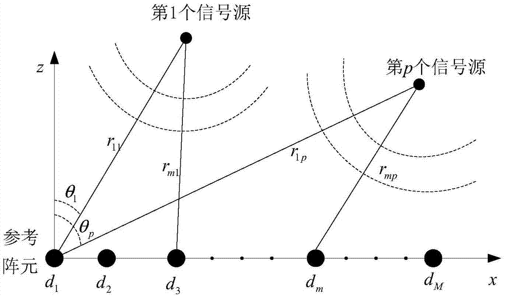
[0037] Step 1: Randomly arrange M antennas within the range of [0, D] meters on the x-axis in the Cartesian coordinate system to form a sparse array. The position is generated as follows: 1 is arranged at position 0 and position D. Array elements and their positions are set to d 1 With d M , Namely d 1 = 0, d M =D, fixed array aperture. Then randomly generate M-2 numbers in a uniform distribution in the range of (0, D), and sort them from small to large, and arrange the remaining M-2 array elements at the positions represented by the M-2 random numbers. , And suppose the positions of the array elements are respectively d 2 ,...,D m ,..., d M-1 .

[0038] Step 2: Start with d 1 The array element at the position is the reference array element. Considering that P near-field uncorrelated target signal sources are incident on the array generated in step 1, for any p = 1, 2, ..., P, use (r p...


PUM


Abstract

The invention discloses a thinned array near-field passive location amplitude and phase error correction method, and relates to the technical field of phased array radar. The method comprises the following steps: under the condition that a target is located in a near field, fixing the pitch angle Phi, alternately and cyclically estimating the distance and azimuth angle of the target until the two parameters converge to the real values, and taking the position as the initial position of error correction; then, carrying out one-dimensional search of the azimuth angle of the target, correcting the array amplitude and phase error using an amplitude and phase error self-correction method, and estimating an array amplitude and phase error matrix gamma(theta) and the first iteration value theta' of the azimuth angle; estimating an array amplitude and phase error matrix gamma(r) and the first iteration value of the distance of the target; and carrying out loop iteration until ||gamma(theta)-gamma(r)||<epsilon2, namely, the estimated values of the parameters converge to the real values. Array element positions are arranged randomly and sparsely within a certain arraying range, the same angle resolution can be achieved with only a small number of array elements, and the cost can be reduced in practical engineering.

Description

Technical field [0001] The invention relates to the technical field of phased array radars, in particular to an array error correction method for passive positioning. Background technique [0002] Compared with the conventional uniform linear array, the sparse array uses the same element to increase the aperture of the array and achieve higher resolution with fewer elements, thereby simplifying the array structure and reducing the cost. At present, sparse array antennas are being used more and more widely in fields such as satellite receiving antennas that resist environmental interference, high-frequency ground radar antennas, and interference arrays in radio astronomy. In addition, the direction of arrival (Direction of Arrival, DOA) estimation is widely used in radar and other fields. Usually high-resolution DOA estimation array processing is based on the ideal array signal model. However, in actual engineering applications, the hardware parameters of each channel are differen...

Claims


Application Information

Patent Timeline
Patent Type & Authority Applications(China)
IPC IPC(8): G01S7/40
CPCG01S7/40
Inventor 崔国龙杨诗倩高尚伟余显祥孔令讲杨晓波易伟张天贤
Owner UNIV OF ELECTRONICS SCI & TECH OF CHINA
Why Eureka
Try Eureka