Display device

A display device and display surface technology, applied in nonlinear optics, instruments, optics, etc., can solve the problems of high temperature, uneven color, and uneven brightness of light-emitting diodes, and achieve uniform brightness, reduce production costs, and improve recovery rates. Effect

Active Publication Date: 2016-03-30
AU OPTRONICS CORP
View PDF6 Cites 7 Cited by
  • Summary
  • Abstract
  • Description
  • Claims
  • Application Information

AI Technical Summary

Problems solved by technology

[0004] One of the main purposes of the present invention is to provide a display device to solve the above-mentioned problems of uneven color, uneven brightness, high temperature of light-emitting diodes and low recovery rate

Method used


Image

  • Display device
  • Display device
  • Display device

Examples


no. 1 example

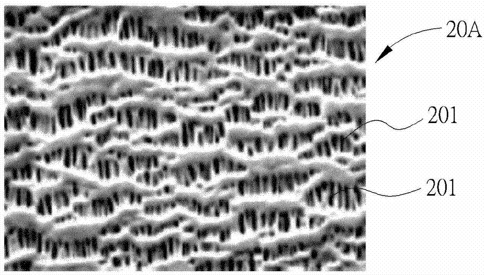
[0085] Please refer to Figure 10 and Figure 11 , Figure 10 shows a schematic cross-sectional view of a display device according to a fourth embodiment of the present invention, Figure 11 A schematic diagram of a porous layer according to a fourth embodiment of the present invention is shown, Figure 11A An enlarged schematic view of the pores in the porous layer according to the fourth embodiment of the present invention is shown. like Figure 10 , Figure 11 and Figure 11A As shown, this embodiment provides another display device 10C. Compared with the first embodiment, the porous layer 20B of the backlight module 14C of this embodiment further includes a plurality of microparticles 42A and a plurality of second quantum dot phosphors 44, the microparticles 42A are arranged in the pores 201, and the second quantum dots Phosphor powder 44 is arranged and distributed in the microparticles 42A. Microparticles 42A can include PMMA, MS, PC, PET, PP, PE, oxides or a mix...


PUM


Abstract

The invention provides a display device, comprising a display panel and a backlight module. The backlight module comprises a light source, a fluorescence film and a multi-hole layer. The fluorescence film is arranged on the back side of the display panel and comprises a plurality of quantum dot phosphors. The multi-hole layer is arranged between the fluorescence film and the display panel, covers the fluorescence film, and comprises a plurality of holes. The multi-hole layer is arranged between the fluorescence film and the display panel, or the fluorescence film is internally provided with the multi-hole layer, thereby improving the recycling efficiency of the first light ray generated by the light source, and furthermore increasing the number and brightness of the second light ray generated by the light source, and reducing the manufacturing cost of the backlight module.

Description

technical field [0001] The invention relates to a display device, in particular to a display device which utilizes a porous layer to improve the conversion efficiency of quantum dot fluorescent powder. Background technique [0002] Liquid crystal display devices have been widely used in electronic products such as notebook computers, digital cameras, mobile phones, and LCD TVs. However, since the liquid crystal display devices are not self-illuminating, a backlight module is required for the display function. [0003] With the improvement of the technical level of light-emitting diode components, light-emitting diodes with the advantages of small size, low operating current, low power consumption, long life and low cost have gradually replaced cold cathode fluorescent lamps (CCFL) as the light source of the backlight module. Since a single light-emitting diode can only produce monochromatic light, it is necessary to use red light-emitting diodes, green light-emitting diodes,...

Claims


Application Information

Patent Timeline
Patent Type & Authority Applications(China)
IPC IPC(8): G02F1/13357
CPCG02F1/133609G02F1/133611G02F1/133614
Inventor 陈明伦陈重廷王明政
Owner AU OPTRONICS CORP
Why Eureka
Try Eureka