Ultrasonic Motor Optimal Frequency Tracking Control System and Control Method for Keeping Minimum Input Power

An ultrasonic motor, input power technology, applied in piezoelectric effect/electrostrictive or magnetostrictive motors, generators/motors, electrical components, etc., can solve the problem that the ultrasonic motor cannot be guaranteed to work in an optimal working state. , to achieve the effect of stable characteristics, small input power, and improved stable characteristics

Inactive Publication Date: 2017-11-03
HARBIN INST OF TECH
View PDF3 Cites 0 Cited by
  • Summary
  • Abstract
  • Description
  • Claims
  • Application Information

AI Technical Summary

Problems solved by technology

[0006] The purpose of the present invention is to solve the problem that the existing technology cannot guarantee the continuous and stable operation of the ultrasonic motor in the optimal working state, and provides a tracking control method for the optimal frequency of the ultrasonic motor that keeps the input power minimum

Method used


Image

  • Ultrasonic Motor Optimal Frequency Tracking Control System and Control Method for Keeping Minimum Input Power
  • Ultrasonic Motor Optimal Frequency Tracking Control System and Control Method for Keeping Minimum Input Power
  • Ultrasonic Motor Optimal Frequency Tracking Control System and Control Method for Keeping Minimum Input Power

Examples


specific Embodiment approach 1

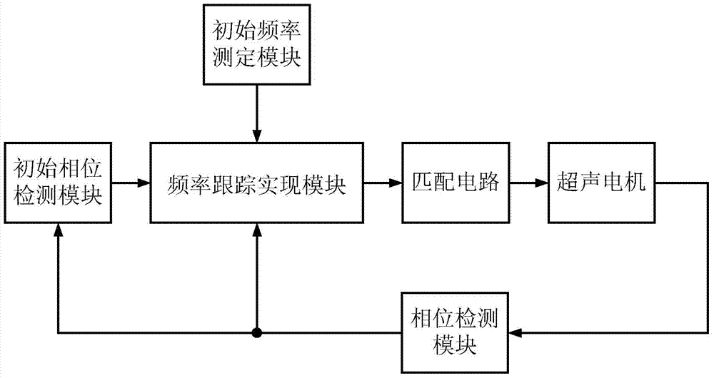
[0025] Specific implementation mode one: the following combination figure 1 Describe this embodiment, the optimal frequency tracking control system of an ultrasonic motor that keeps the minimum input power described in this embodiment, the control system includes an initial frequency measurement module, an initial phase detection module, a phase detection module, a frequency tracking realization module and a matching circuit;

[0026] The initial frequency measurement module is used to determine the working frequency corresponding to the optimal working state of the ultrasonic motor, and use this working frequency as the initial frequency;

[0027] The initial phase detection module is used to determine the initial phase of the ultrasonic motor in the first sampling period when the ultrasonic motor works at the initial frequency;

[0028] The phase detection module is used to detect the phase difference between the input current and voltage of the ultrasonic motor in real time...

specific Embodiment approach 2

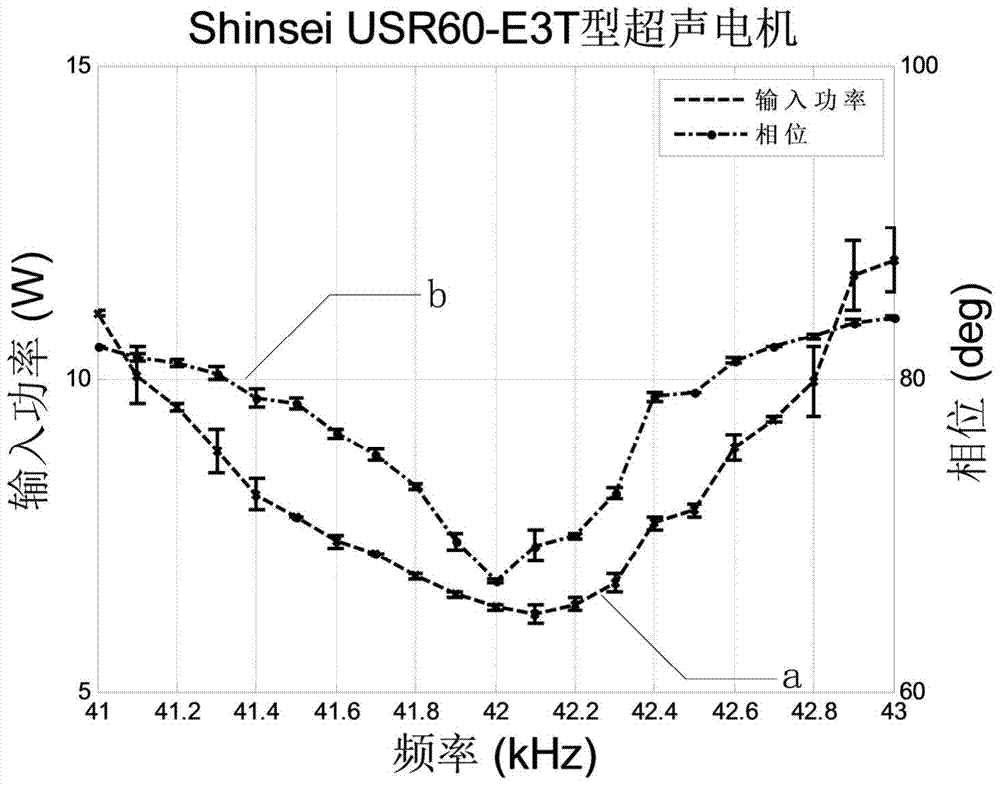
[0033] Specific implementation mode 2: This implementation mode further explains the implementation mode 1. The specific process of determining the initial frequency by the initial frequency measurement module is as follows:

[0034] Keep the ultrasonic motor at a constant speed, measure the power spectrum characteristics of the ultrasonic motor, and the operating frequency corresponding to the minimum input power point is the initial frequency.

specific Embodiment approach 3

[0035] Specific implementation mode three: this implementation mode further explains implementation mode one, and the specific process for the frequency tracking implementation module to generate the driving voltage signal of the ultrasonic motor is as follows:

[0036] Collect the phase sampling value of the current sampling period, make a difference between the phase sampling value and the initial phase value, convert the difference into the change in the frequency value of the driving signal, and make the difference between the variable frequency value and the working frequency obtained in the previous sampling period, and the obtained The difference value is used as the frequency value of the drive motor signal, through power amplification, the frequency value is generated into a two-phase quadrature drive voltage signal.


PUM


Abstract

The invention provides a tracking control system and a control method for the optimal frequency of an ultrasonic motor on the premise of maintaining the minimum input power, belongs to the technical field of two-phase ultrasonic motor driving control, and aims to solve a problem that the ultrasonic motor cannot be guaranteed to work in the optimal working condition continuously and stably in the prior art. In the system, an initial frequency measurement module is used for determining working frequency corresponding to the optimal working condition of the ultrasonic motor; an initial phase detection module is used for determining an initial phase of the ultrasonic motor in a first sampling period when the ultrasonic motor works with an initial frequency; a phase detection module is used for detecting a real-time phase value of the ultrasonic motor in real time to drive a frequency tracking realization module to work; the frequency tracking realization module is used for generating a driving voltage signal; and a matching circuit is used for performing filtering and magnification on the driving voltage signal, and then generating a signal loaded onto the ultrasonic motor. The system and the method are used for motor driving control.

Description

technical field [0001] The invention belongs to the technical field of two-phase ultrasonic motor drive control. Background technique [0002] As a typical piezoelectric actuator, the performance of the ultrasonic motor is directly limited by the performance of the piezoelectric material. Due to the combined effect of various losses in the piezoelectric ceramic, on the contact interface of the stator and rotor, and in the metal elastic body of the stator and rotor, during operation, more heat will be generated inside the ultrasonic motor, which will affect the motor to a greater extent. Many characteristic parameters of piezoelectric materials, including compliance constant, piezoelectric coefficient and dielectric constant, will affect the performance of ultrasonic motors. In order to suppress the adverse effect on the output performance caused by the temperature change characteristics of the motor, the researchers have developed an effective frequency tracking control tec...

Claims


Application Information

Patent Timeline
Patent Type & Authority Patents(China)
IPC IPC(8): H02N2/14
CPCH02N2/142
Inventor 史维佳赵辉马杰姚郁刘晓坤
Owner HARBIN INST OF TECH
Why Eureka
Try Eureka