Permanent magnet embedded type rotating electric machine

A technology of rotating electrical machines and permanent magnets, which is applied in the direction of magnetic circuit rotating parts, magnetic circuits, electromechanical devices, etc., which can solve the problems of inability to effectively cool permanent magnets and achieve effective cooling

Active Publication Date: 2016-03-30
MITSUBISHI ELECTRIC CORP
View PDF12 Cites 15 Cited by
  • Summary
  • Abstract
  • Description
  • Claims
  • Application Information

AI Technical Summary

Problems solved by technology

[0010] In addition, in the conventional permanent magnet embedded rotating electrical machine described in Patent Document 2, the flow path of cooling oil is formed between the outer yoke portion and the i...

Method used


Image

  • Permanent magnet embedded type rotating electric machine
  • Permanent magnet embedded type rotating electric machine
  • Permanent magnet embedded type rotating electric machine

Examples


Embodiment approach 1

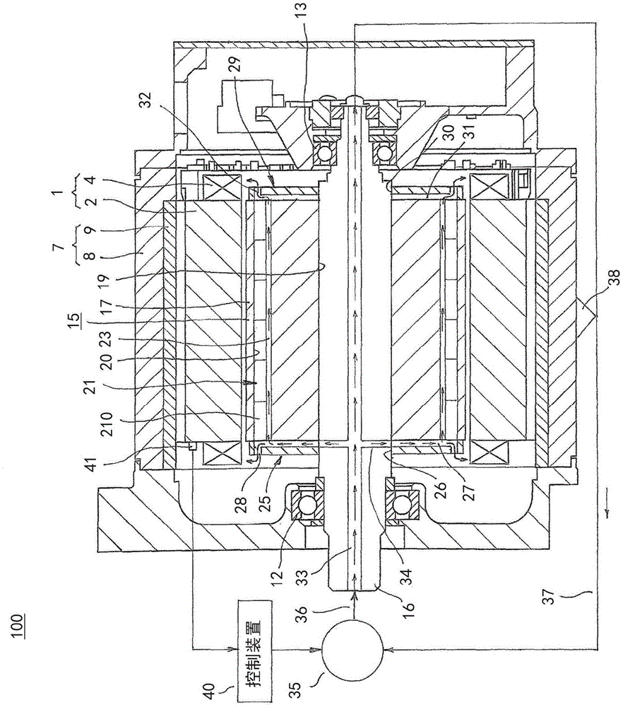
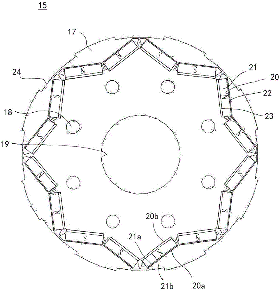
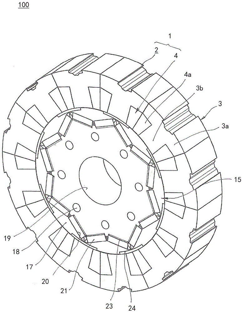
[0028] figure 1 is a sectional view showing the permanent magnet embedded rotating electrical machine according to Embodiment 1 of the present invention, figure 2 It is an end view showing the rotor core in the permanent magnet embedded rotating electrical machine according to Embodiment 1 of the present invention, image 3 It is a perspective view illustrating a state in which a rotor core is assembled in a stator of a permanent magnet embedded rotating electrical machine according to Embodiment 1 of the present invention, Figure 4 It is a flowchart showing a drive control method of the external oil delivery equipment in the permanent magnet embedded rotating electrical machine according to Embodiment 1 of the present invention. also, figure 1 The middle arrows indicate the flow direction of cooling oil.

[0029] Figure 1 to Figure 3 Among them, the permanent magnet embedded type rotating electrical machine 100 includes: an annular stator 1; a cylindrical frame 7 that ...

Embodiment approach 2

[0064] Figure 5 It is a sectional view showing a permanent magnet embedded rotating electrical machine according to Embodiment 2 of the present invention.

[0065] Figure 5 Here, the in-shaft flow path 33A is formed to extend from one end in the axial direction at the axial center of the shaft 16A to a position radially below the introduction flow path 27 formed in the first end plate 25 . Furthermore, the branch flow path 34 is formed on the shaft 16A so as to communicate with the other axial end of the in-shaft flow path 33A and the introduction flow path 27 .

[0066] In addition, other configurations are configured in the same manner as in the first embodiment described above.

[0067] In the permanent magnet embedded rotating electrical machine 101 configured in this way, the in-shaft flow path 33A is formed only on the front side of the shaft 16A, so that the cost of the shaft 16A can be reduced.

Embodiment approach 3

[0069] Image 6 It is a cross-sectional view showing a permanent magnet embedded rotating electrical machine according to Embodiment 3 of the present invention.

[0070] Image 6 Among them, the cross-sectional areas of the first discharge passage 28 , the cooling flow passage 23 , and the second discharge passage 32 become larger in the order of the first discharge passage 28 , the cooling flow passage 23 , and the second discharge passage 32 .

[0071] In addition, other configurations are configured in the same manner as in the first embodiment described above.

[0072] In the permanent magnet embedded rotating electrical machine 102 thus constituted, the flow passage sectional area of ​​the first discharge passage 28 is smaller than the passage cross-sectional area of ​​the cooling passage 23, and therefore, the cooling oil flowing through the introduction passage 27 is discharged from the first discharge passage 28. The outflow amount of the discharge passage 28 is rest...


PUM


Abstract

The purpose of this invention is to obtain a permanent magnet embedded type rotating electric machine in which the amount of magnetic flux of a permanent magnet can be prevented from reducing and the permanent magnet can be effectively cooled. In the permanent magnet embedded type rotating electric machine, a rotor (15) has: a rotor iron core (17) constructed by laminating and integrating magnetic steel sheets and firmly fixed to a shaft; a plurality of magnet housing openings (20) each formed so as to penetrate in an axial direction on the outer circumferential side of the rotor iron core (17) and disposed in a circumferential direction; and permanent magnets (21) housed in the respective magnet housing openings (20). An adhesive agent (22) is disposed only between the outside wall surface (20a) of the inner wall surfaces of each of the magnet housing openings (20), which is positioned outward in the radial direction, and the outside surface (21a) of the surfaces of each of the permanent magnets (21), which is positioned outward in the radial direction. The permanent magnets (21) are each disposed one-sided to the outside wall surface (20a) of each of the magnet housing openings (20) and fixed. A cooling flow path (23) through which a refrigerant flows is constituted by the inside surface (21b) of the surfaces of each of the permanent magnets (21), which is positioned inward in the radial direction, and the inside wall surface (20b) of the inner wall surfaces of each of the magnet housing openings (20), which is positioned inward in the radial direction.

Description

technical field [0001] The present invention relates to a permanent magnet embedded rotating electrical machine in which permanent magnets are embedded in the outer peripheral side of a rotor core, and more particularly to a cooling structure for the permanent magnets embedded in the rotor core. Background technique [0002] In a conventional embedded permanent magnet rotating electrical machine, a permanent magnet is arranged in a cavity formed to extend in the direction of the rotation axis in the rotor core, and an insulating member is formed to cover the entire inner wall surface of the cavity. The permanent magnet is cooled by allowing a cooling liquid to flow through a cooling channel formed by the surface of the magnet and the inner surface of the insulating member (for example, refer to Patent Document 1). [0003] In addition, in another conventional permanent magnet embedded rotating electrical machine, an annular outer yoke portion in which permanent magnets are e...

Claims


Application Information

Patent Timeline
IPC IPC(8): H02K1/32H02K1/27H02K9/19H02K3/24
CPCH02K9/19H02K1/2766H02K1/32H02K11/25H02K1/16H02K1/30
Inventor 堀井雅树井上正哉橘田佳明
Owner MITSUBISHI ELECTRIC CORP
Why Eureka
Try Eureka