Machining control method for aero-engine fuel nozzle part

An aero-engine and fuel nozzle technology, applied in aircraft parts, transportation and packaging, etc., can solve the problems of difficulty in ensuring dimensional accuracy, high difficulty in parts clamping, low work efficiency, etc., to reduce tool costs, high efficiency and short cycle, Good for chip removal

Active Publication Date: 2016-04-06
CHINA HANGFA SOUTH IND CO LTD
View PDF7 Cites 26 Cited by
  • Summary
  • Abstract
  • Description
  • Claims
  • Application Information

AI Technical Summary

Problems solved by technology

[0006] The invention provides a processing control method for aero-engine fuel nozzle parts to solve the problem that the existing aero-engine fuel nozzle parts need to be processed through multiple processes, and the parts are difficult to clamp. Guarantee the dimensional accuracy after processing; roughness control is performed manually, the work efficiency is low, the workload is heavy, and it is difficult to guarantee the technical problems of dimensional accuracy

Method used


Image

  • Machining control method for aero-engine fuel nozzle part
  • Machining control method for aero-engine fuel nozzle part
  • Machining control method for aero-engine fuel nozzle part

Examples


Embodiment Construction

[0024] The embodiments of the present invention will be described in detail below with reference to the accompanying drawings, but the present invention can be implemented in various ways defined and covered below.

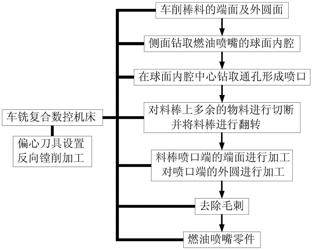
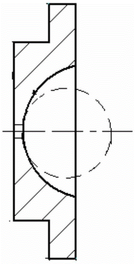
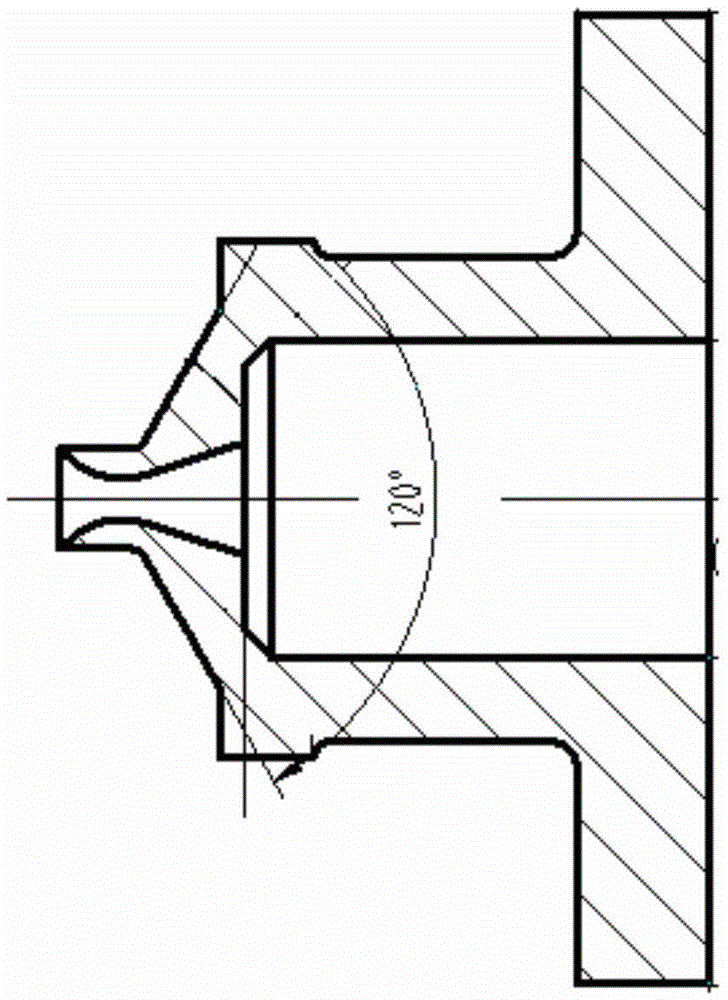
[0025] figure 1 It is a structural block diagram of a processing control method for aero-engine fuel nozzle parts in a preferred embodiment of the present invention; figure 2 It is one of the structural schematic diagrams of the fuel nozzle parts of the aero-engine in the preferred embodiment of the present invention; image 3 It is the second structural schematic view of the fuel nozzle part of the aero-engine in the preferred embodiment of the present invention.

[0026] like figure 1 As shown, the processing control method for aero-engine fuel nozzle parts in this embodiment uses a turn-milling compound numerical control machine tool to clamp the material bar at one time and perform all processes; adopts eccentric tool setting and reverse boring Processing ...


PUM

PropertyMeasurementUnit
radiusaaaaaaaaaa
radiusaaaaaaaaaa
lengthaaaaaaaaaa

Abstract

The invention discloses a machining control method for an aero-engine fuel nozzle part. A turn-mill combination numerical control machine tool is adopted for carrying out one-time clamping on a bar, and machining in all procedures is carried out; the bar is clamped, the end face and the outer circle face of the bar are turned, a spherical inner cavity of a fuel nozzle is drilled in the side face of the bar, and a through hole is drilled in the center of the spherical inner cavity to form a nozzle; the outer circle face of the machined bar is clamped, residual materials on the bar are cut off, and the bar is turned over; the outer circle face of the turned-over bar is clamped, the end face of the nozzle end of the bar is machined, and the outer circle of the nozzle end is machined; and burrs are removed, and the fuel nozzle part is obtained. The rigidity of a tool is increased through the eccentric structure of the tool, and the cost of the tool is reduced. The reverse boring technology is adopted, chip discharging is facilitated, pulling and scratching caused by scrap iron to an oil spray hole are reduced, and it is guaranteed that the flow test performance parameters of the nozzle are qualified. The machining control method is suitable for machining control over nozzle parts of various aero-engines and auxiliary power device engines.

Description

technical field [0001] The invention relates to the technical field of processing nozzle parts of aero-engines, in particular to a processing control method for fuel nozzle parts of aero-engines. Background technique [0002] Most of the existing aero-engine fuel nozzle parts are small or miniature parts. [0003] The structural characteristics of the small-size centrifugal nozzle nozzle are that the inner cavity is spherical or conical, the profile is a variable section, and the variable section is connected with the micro-sized oil injection hole or step hole, and the dimensional accuracy is high. There are technical requirements between the end faces. The conventional process is processed by multiple processes such as turning, milling, grinding, clamping, grinding, and polishing. Due to the small size, the positioning surface and clamping surface of the part are small in size, which is not easy to install. Clamping, the size and technical conditions of the parts clamped ...

Claims


Application Information

Patent Timeline
Patent Type & Authority Applications(China)
IPC IPC(8): B23P15/00
CPCB23P15/00B23P2700/01
Inventor 黄强飞黄倩陈艳芳宁雄施跃幸万坤邓巍吴超
Owner CHINA HANGFA SOUTH IND CO LTD
Why Eureka
Try Eureka