Door lock device for sliding doors
A door lock and lock frame technology, applied in the field of mechanical components, can solve the problems of impact kinetic energy roller, lock fork and its connecting mechanism damage, unstable operation of lock and connecting mechanism, etc., achieves fast reset speed, simple structure, and prevents jamming effect of the phenomenon
- Summary
- Abstract
- Description
- Claims
- Application Information
AI Technical Summary
Problems solved by technology
Method used
Image

Examples
Embodiment 1
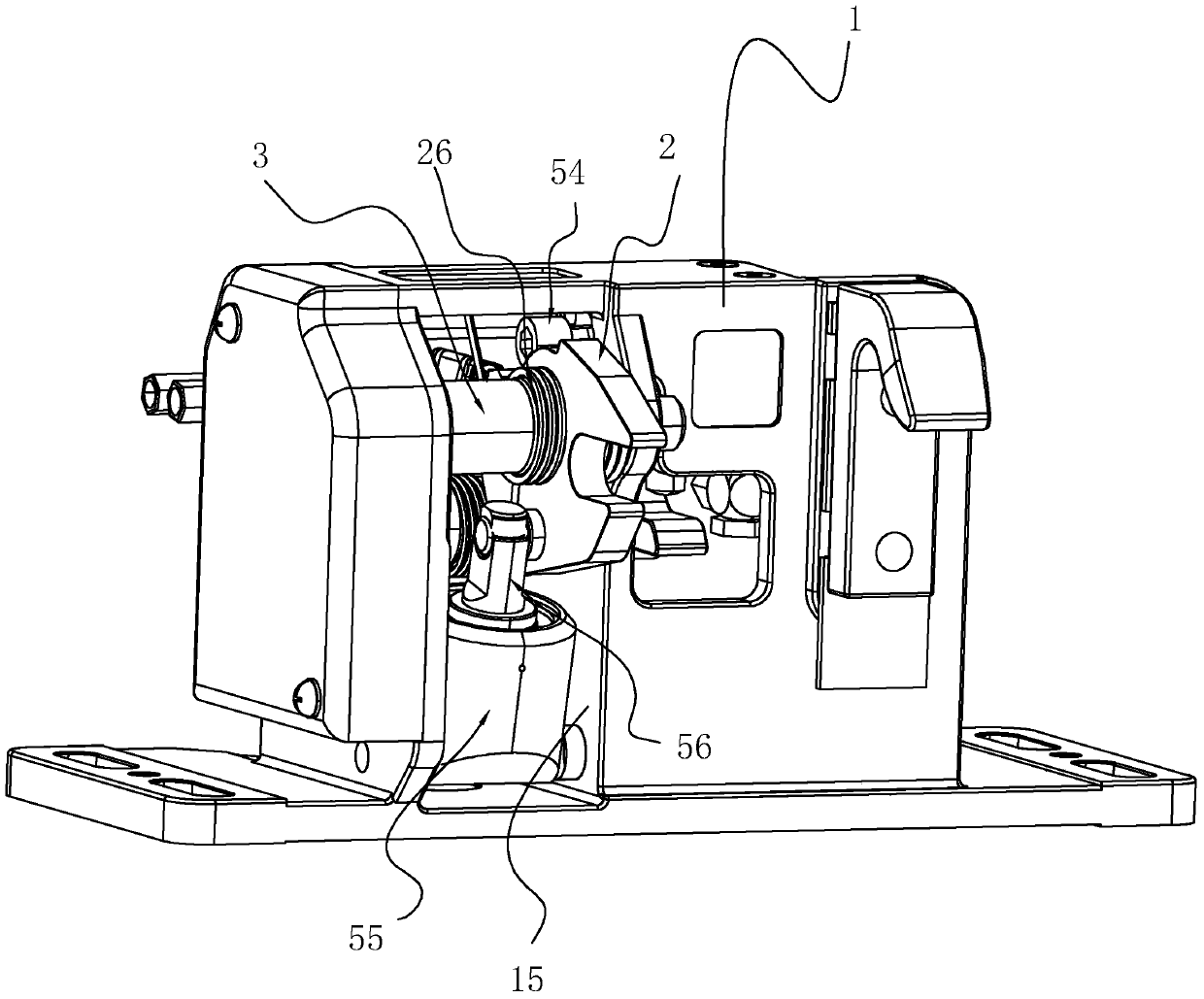
[0047] Embodiment one, refer to figure 1 and figure 2 , the lock fork 2, the lock fork 2 is rotatably connected to the lock frame 1 through the rotating shaft 3. Figure 5 and Figure 7 , the rotating shaft 3 is plugged into the lock hole 24 of the lock fork 2, and a bearing 25 is installed in the lock hole 24. The number of the bearings 25 is two, and the two ends of the lock fork 24 are clamped, so that the lock fork 2 is reduced. Frictional resistance to rotation. Figure 5 and Figure 6 Among them, the left end of the lock fork 2 is provided with a cutout that matches the roller 8, and by rotating the lock fork 2 upward, the roller 8 in the lock fork 2 rotates upward to realize locking; and after the lock fork 2 resets downward, unlocking is realized . A cylinder 55 is arranged below the lock fork 2, and the push rod of the cylinder 55 is hinged with the lock fork 2 through a connecting shaft; 1 on the frame, and the rod cavity of the cylinder 55 is provided with a ...
Embodiment 3
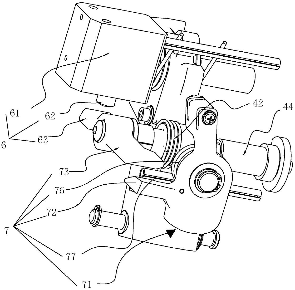
[0058] Embodiment three, refer to figure 1 , image 3 and Figure 10 , the automatic unlocking mechanism 6 includes a piston cylinder 61, the piston cylinder 61 fixes the cylinder 61 on the cover plate position of the lock frame 1 through two screws, the piston rod 63 of the piston cylinder 61 faces downward, and the first square shaft 411 is sleeved Connecting plate 62 is arranged, and when piston rod 63 is ejected, its end connects connecting plate 62, makes connecting plate 62, bearing shaft 41 and dial 431 rotate synchronously, and it makes dial 431 spin out lock groove 22, reaches the purpose of unblanking. If the piston rod 63 and the connecting plate 62 are hinged, the resistance when the bearing torsion spring 42 is reset will increase, reducing the sensitivity when the bearing shaft 41 is reset, and the gap between the piston rod 63 and the connecting plate 62 effectively solves the above-mentioned problem. Technical issues with low sensitivity.
Embodiment 4
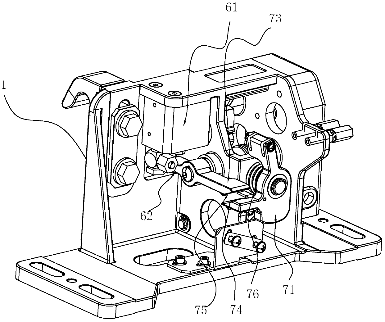
[0059] Embodiment four, refer to image 3 and Figure 4 , the manual unlocking mechanism 7 includes a swivel frame 71, the swivel frame 71 is installed on the lock frame 1 through a rotating shaft, the swivel frame 71 is fixed with a paddle 72, the connecting plate 62 is extended with a long arm plate 73, and the long arm plate 73 is larger than The length of the connecting plate 62 makes the arm of the manual operation longer and the manual unlocking easier;
[0060] The upper surface of the plectrum 72 is provided with a first slope 74, and the long arm plate 73 is provided with a second slope 75, the first slope 74 can fit the second slope 75, the design of the first slope 74 and the second slope 75 The contact area between the plectrum 72 and the long-arm plate 73 is increased, so that the force of the long-arm rod is more stable during the collision process, and the rotation accuracy of the bearing shaft 41 is higher.
[0061] Manual unlocking steps: the pick 72 and the...
PUM
 Abstract
Description
Claims
Application Information
 - R&D
- Intellectual Property
- Life Sciences
- Materials
- Tech Scout
- Unparalleled Data Quality
- Higher Quality Content
- 60% Fewer Hallucinations
Browse by: Latest US Patents, China's latest patents, Technical Efficacy Thesaurus, Application Domain, Technology Topic, Popular Technical Reports.
© 2025 PatSnap. All rights reserved.Legal|Privacy policy|Modern Slavery Act Transparency Statement|Sitemap|About US| Contact US: help@patsnap.com