
Compression-type stainless-steel corrugated pipe for gas pipeline and assembly method of compression-type stainless-steel corrugated pipe

A technology of gas pipeline and assembly method, which is applied in the direction of hose connection device, pipe/pipe joint/pipe fitting, sealing surface connection, etc., can solve the problems of affecting the appearance, corrosion of metal parts, and inflexible connection methods.

Inactive Publication Date: 2016-04-06
NINGBO SUOLI PIPE
View PDF8 Cites 7 Cited by
  • Summary
  • Abstract
  • Description
  • Claims
  • Application Information

AI Technical Summary

Problems solved by technology

[0004] However, the corrugated pipes used in the prior art either use threaded joints at both ends or Green joints at both ends to connect the main gas pipeline and the gas cooker. Although the connection is convenient and reliable, it can completely prevent leakage and avoid gas leakage. And cause poisoning, explosion accident hidden danger, but the connection method is not flexible enough; at the same time, in order to make the corrugated pipe can be connected with the hard pipe made of steel or PVC material in the existing technology, the joints of engineering prefabrication or pressure A joint with a tight sleeve, but the above construction suffers from installation and functional deficiencies:
[0020] The outer side of the metal bellows in the prior art lacks a coating layer, and the metal part of the bellows will be exposed outside, which will affect the appearance. This will also cause the metal part to be corroded by the external medium, and will be cut by external sharp tools at the same time. cause leakage
In the prior art, there is only an introduction to the installation method of the bellows without the peripheral coating layer, and no inspiration is given for the installation method of the bellows using the peripheral coating layer

Method used


Image

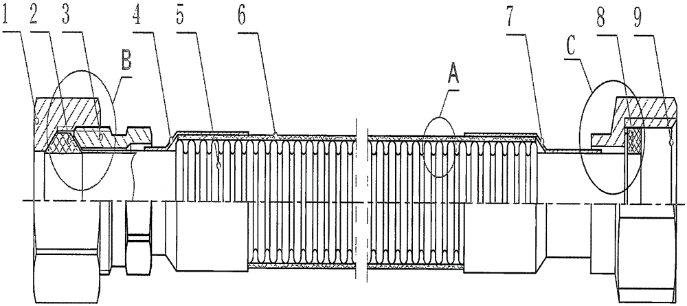
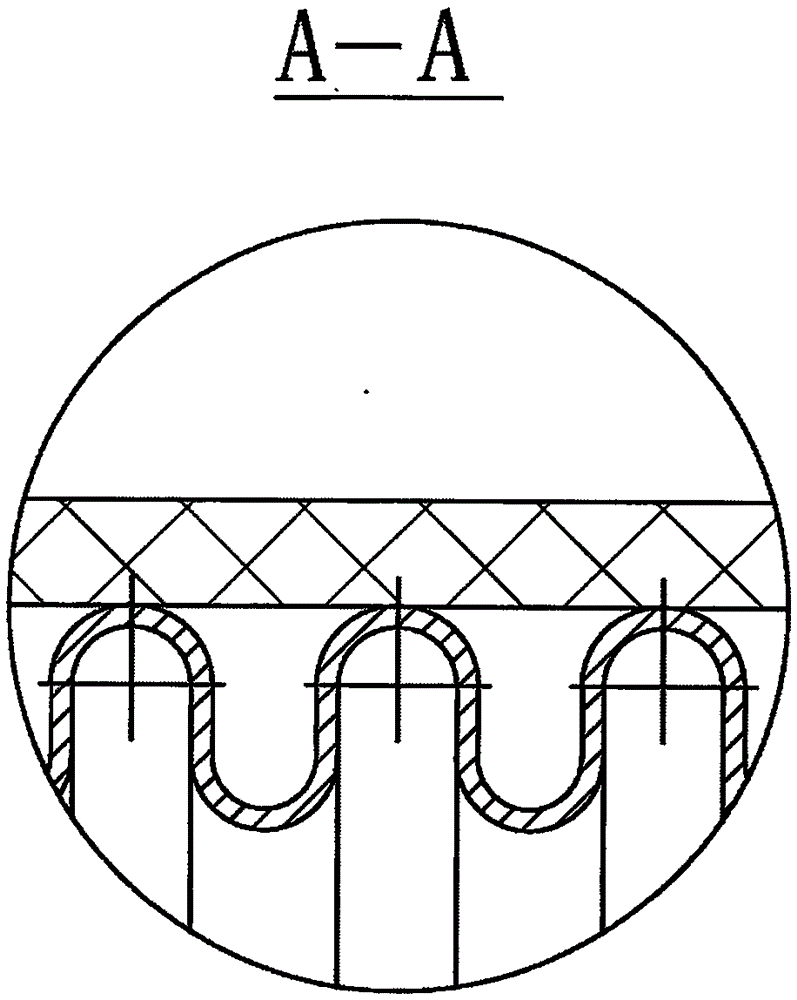
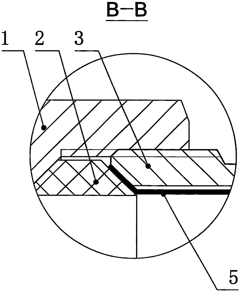
  • Compression-type stainless-steel corrugated pipe for gas pipeline and assembly method of compression-type stainless-steel corrugated pipe
  • Compression-type stainless-steel corrugated pipe for gas pipeline and assembly method of compression-type stainless-steel corrugated pipe
  • Compression-type stainless-steel corrugated pipe for gas pipeline and assembly method of compression-type stainless-steel corrugated pipe

Examples


Embodiment Construction

[0045] In order to make the objectives, technical solutions and advantages of the present invention clearer, the technical solutions in the embodiments of the present invention will be described in more detail below in conjunction with the drawings in the embodiments of the present invention. In the drawings, the same or similar reference numerals denote the same or similar elements or elements having the same or similar functions throughout. The described embodiments are some, but not all, embodiments of the invention. The embodiments described below by referring to the figures are exemplary and are intended to explain the present invention and should not be construed as limiting the present invention. Based on the embodiments of the present invention, all other embodiments obtained by persons of ordinary skill in the art without creative efforts fall within the protection scope of the present invention. Embodiments of the present invention will be described in detail below ...


PUM


Abstract

The invention discloses a compression-type stainless-steel corrugated pipe for a gas pipeline and an assembly method of the compression-type stainless-steel corrugated pipe. The stainless-steel corrugated pipe comprises a first copper nut, a tapered sealing washer, a male adapter, a short steel sleeve, a corrugated pipe, a covering layer, a long steel sleeve, a flat sealing washer and a second copper nut. When used for connecting a main gas pipeline and a gas cooker, the stainless-steel corrugated pipe has the advantages of being applicable to various pipeline connectors, convenient to mount and replace and simple in mounting and replacing step, providing a reliable locking force and a good sealing property, being firm, safe and effective in connection, resisting high and low temperature, having an attractive appearance, having the outer covering layer with good corrosion resistance and a long service life, and being capable of being used in combination with a threaded connector and a corrugated connector freely.

Description

technical field [0001] The invention relates to a corrugated pipe and an assembly method thereof, in particular to a compressed stainless steel corrugated pipe used for a gas pipeline and an assembly method thereof. Background technique [0002] The corrugated pipe for gas appliance connection is specially used for connecting the main gas pipeline, and the flexible connection pipeline for transmitting gas sources such as gas, coal gas, liquefied petroleum gas or biogas and fixed gas stoves, which has been very common in the prior art. The corrugated pipe is made of metal material and has a spiral corrugated metal flexible connecting pipe. The corrugated pipe has a certain degree of flexibility and can be bent at will without bending. It also has the advantages of hard metal pipes and will not It is inconvenient to install and replace the rubber tube, and it will not be easily blocked in a bent state, and will not have poor corrosion resistance, easy aging, short service life...

Claims


Application Information

Patent Timeline
Patent Type & Authority Applications(China)
IPC IPC(8): F16L19/03F16L33/26
CPCF16L19/0206F16L33/26
Inventor 向磊
Owner NINGBO SUOLI PIPE
Learn More