
Positioning method for phase-sensitive optical time-domain reflectometry optical fiber sensing system

A fiber optic sensing system and phase-sensitive light technology, applied in the direction of wave/particle radiation, instruments, measuring devices, etc., can solve the problems of low false alarm rate, complex signal processing algorithm, etc., to overcome false alarms and avoid polarization fading Effect

Active Publication Date: 2019-06-04
SHANGHAI UNIV
View PDF1 Cites 0 Cited by
  • Summary
  • Abstract
  • Description
  • Claims
  • Application Information

AI Technical Summary

Problems solved by technology

Rao Yunjiang from Chengdu University of Electronic Science and Technology (Wu Xunwei, Wu Huijuan, Rao Yunjiang, Wu Yu, Zhao Tian, ​​Low false alarm rate distributed fiber optic fence intrusion monitoring system based on comprehensive judgment of multiple wavelet decomposition methods, Acta Photonica Sinica, 2011, 40(11); Distributed optical fiber fence intrusion detection and location method based on Ф-OTDR, Chinese invention patent, inventors: Wu Huijuan, Wu Xunwei, Li Shanshan, Rao Yunjiang, application announcement number: CN 102280001 A) proposed a comprehensive judgment technology using multiple wavelet decomposition methods, passed The difference in wavelet results of different orders can reduce the false alarm rate of fence intrusion. This technology requires complex signal processing algorithms

Method used


Image

  • Positioning method for phase-sensitive optical time-domain reflectometry optical fiber sensing system
  • Positioning method for phase-sensitive optical time-domain reflectometry optical fiber sensing system
  • Positioning method for phase-sensitive optical time-domain reflectometry optical fiber sensing system

Examples


Embodiment 1

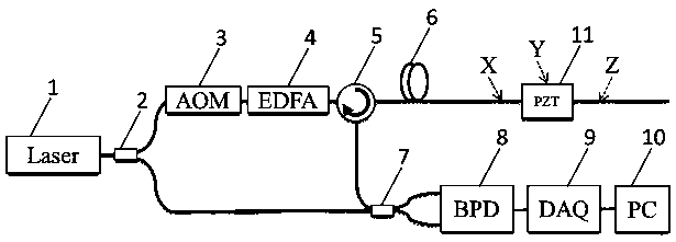
[0027] see figure 1 , phase-sensitive optical time-domain reflection fiber optic sensing system, including narrow linewidth laser 1, 1´2 fiber coupler 2, acousto-optic modulator 3, erbium-doped fiber amplifier 4, fiber circulator 5, sensing fiber 6, 2 ´2 fiber optic coupler 7, balanced light detector 8, data acquisition card 9, computer 10.

[0028] The components of each part of the system are described as follows:

[0029] Narrow linewidth laser 1, used to generate long coherence length laser;

[0030] 1´2 fiber optic coupler 2, used to divide the laser into two paths, one for the sensing light path, and the other for the reference light path, the optical power of the sensing light path is much greater than that of the reference light path, and the coupling splitting ratio can be selected as 90:10;

[0031] The acousto-optic modulator 3 is used to modulate the laser into a pulsed laser, and at the same time, allow the laser pulse to obtain a frequency shift of a fixed freq...


PUM


Abstract

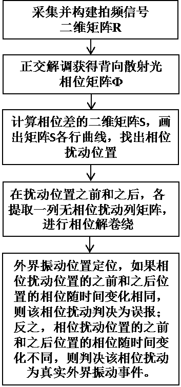
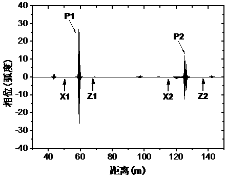
The invention relates to a phase sensitive optical time domain reflection fiber sensing system positioning method, which comprises the steps of collecting beat frequency data signals corresponding to multitime light pulses; obtaining a backward diffusion light phase matrix phi; determining an extraneous vibration disturbance position Y; selecting a position X1, a position Z1, a position X2 and a position Z2 that have no phase disturbance before and after the extraneous vibration disturbance position Y; phase unwrapping the X1, Z1, X2 and Z2 at the corresponding column phase in the backward diffusion light phase matrix phi; and then expanding the phase change to a scope of -infinity to +infinity. If the phase of the position is the same while time passing by before and after the phase disturbance position, the phase disturbance is determined to be a false alarm; otherwise, the phase disturbance is determined to be a real extraneous vibration event. The problem of introducing a fault abnormal phase because of polarization fading or interference fading in a phi-OTDR system application is solved; a high rate of false alarm because of fading is reduced; and an accurate positioning of a real extraneous disturbance event is realized. The method is simple and practical in a normal phi-OTDR fiber distributed sensing system.

Description

technical field [0001] The invention relates to a positioning method for a phase optical fiber sensing system, in particular to a positioning method for a phase-sensitive optical time domain reflection optical fiber sensing system, belonging to the field of optical fiber sensing technology applications. Background technique [0002] Phase-sensitive Optical Time Domain Reflectometry (Phase-sensitive Optical Time Domain Reflectometry, abbreviated as Ф-OTDR or Phase-sensitive OTDR) optical fiber distributed sensing system is used to monitor external vibration disturbance events, and can realize the location of external vibration disturbance events It has the advantages of linear distributed measurement, remote measurement, high sensitivity, strong anti-electromagnetic interference, good insulation, intrinsically safe, light weight and small size, and is widely used. In the field of petrochemical industry, Ф-OTDR can realize the monitoring of anti-damage excavation events of oil...

Claims


Application Information

Patent Timeline
Patent Type & Authority Patents(China)
IPC IPC(8): G01H9/00
CPCG01H9/004
Inventor 庞拂飞贺梦婷梅煊玮张小贝王廷云
Owner SHANGHAI UNIV
Learn More