
Super-resolution fluorescence microscopy device and method based on virtual wave vector modulation

A virtual wave vector and super-resolution technology, applied in the field of confocal microscopy, which can solve the problems of limited fluorescent labeling substances, noise and aberration, and low optical sectioning ability.

Active Publication Date: 2016-04-06
杭州柏纳光电有限公司
View PDF8 Cites 10 Cited by
  • Summary
  • Abstract
  • Description
  • Claims
  • Application Information

AI Technical Summary

Problems solved by technology

These fluorescence super-resolution microscopy methods can achieve super-resolution imaging, but there are three types of problems at the same time: (1) limited fluorescent labeling substances; (2) noise and aberration; (3) low optical sectioning ability

Method used


Image

  • Super-resolution fluorescence microscopy device and method based on virtual wave vector modulation
  • Super-resolution fluorescence microscopy device and method based on virtual wave vector modulation
  • Super-resolution fluorescence microscopy device and method based on virtual wave vector modulation

Examples


Embodiment 1

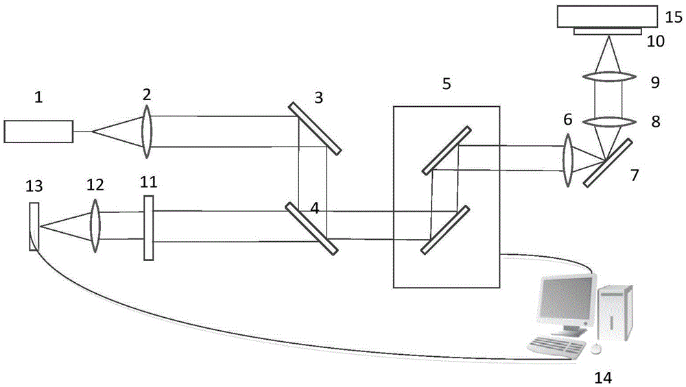
[0081] like figure 1 As shown, a fluorescent super-resolution microscopy device based on virtual wave vector modulation that scans the sample by controlling the scanning galvanometer and the z-axis translation stage, including a laser 1, a lens 2, a mirror 3, a dichroic mirror 4, and a vibrating Mirror scanning system 5, scanning mirror 6, reflecting mirror 7, field mirror 8, microscope objective lens 9, sample 10, z-axis piezoelectric platform 15, filter 11, magnifying imaging system 12, rectangular detector array 13, computer 14.

[0082] use figure 1 The shown setup realizes the two-color microscopy method based on virtual wave vector modulation for the sample, and the process is as follows:

[0083] (1) The laser 1 emits an excitation beam, which is first collimated by the lens 2, reflected by the first mirror 3, reflected by the dichromatic mirror 4, and enters the scanning galvanometer system 5; the excitation light guided by the scanning galvanometer system 5 passes ...

Embodiment 2

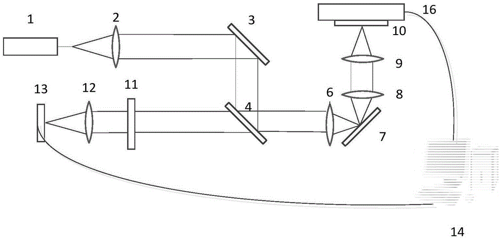
[0089] like image 3 As shown, a fluorescence super-resolution microscopy device based on virtual wave vector modulation that scans samples by controlling a three-dimensional translation stage, including a laser 1, a lens 2, a mirror 3, a dichromatic mirror 4, a scanning mirror 6, and a mirror 7. Field lens 8, microscope objective lens 9, sample 10, three-dimensional translation stage 16, filter plate 11, magnifying imaging system 12, honeycomb coal-shaped detector array 13, computer 14.

[0090] use image 3 The shown setup realizes the two-color microscopy method based on virtual wave vector modulation for the sample, and the process is as follows:

[0091](1) The laser 1 sends an exciting light beam, which is first collimated by the lens 2, reflected by the first mirror 3, reflected by the dichromatic mirror 4, and forms a scanning area on the rear focal plane after the scanning mirror 6; the field mirror 8 and The microscope objective lens 9 jointly forms an imaging syst...


PUM


Abstract

The invention discloses a super-resolution fluorescence microscopy method based on virtual wave vector modulation. The method includes recording optical intensity information of the Airy disk of a point by a detector array when the point of an object is scanned by excited light, with the Airy disk being formed on an image surface, subjecting the array information to virtual wave vector modulation by loading different figure patterns, and adding all point light intensity of the array with the sum being adopted as image information of the scanned point. High-frequency components of sample information, which are originally cut off by imaging system bandwidth, are encoded into modulated image information. After s sample is subjected to two-dimension scanning, an object image after the virtual wave vector modulation is obtained, and a super-resolution object image is reconstituted from the image after modulation through an iterative algorithm. The invention also discloses a super-resolution fluorescence microscopy device based on virtual wave vector modulation. The detector array and the virtual wave vector modulation manner are adopted, so that a same background noise inhibiting effect is achieved and a higher lateral resolution is achieved.

Description

technical field [0001] The invention belongs to the field of confocal microscopy, in particular to a fluorescence super-resolution microscopy method and device based on virtual wave vector modulation. Background technique [0002] The confocal microscope uses the point light source formed by the laser beam through the optical system to scan every point of the focal plane of the objective lens in the sample. The irradiated point on the sample is imaged at the probe pinhole, while the points outside the focal plane are not imaged at the probe pinhole. The image information of the irradiated point on the sample is received point by point by the photodetector after detecting the pinhole, and a fluorescent image is quickly formed on the computer monitor screen. [0003] For example, the patent document whose publication number is CN102830102A provides a kind of confocal microscopy method based on hollow focusing spot excitation, and the laser beam is converted into circularly po...

Claims


Application Information

Patent Timeline
IPC IPC(8): G01N21/64
CPCG01N21/6458
Inventor 匡翠方方月马也刘旭
Owner 杭州柏纳光电有限公司
Learn More